























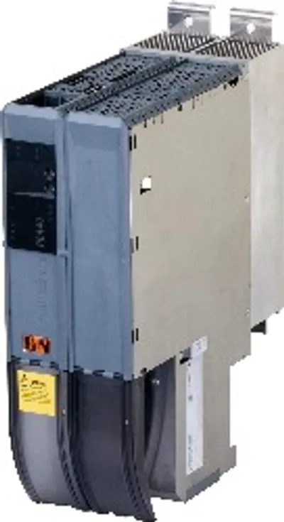
B&R 8BVP0880HC00.008-3
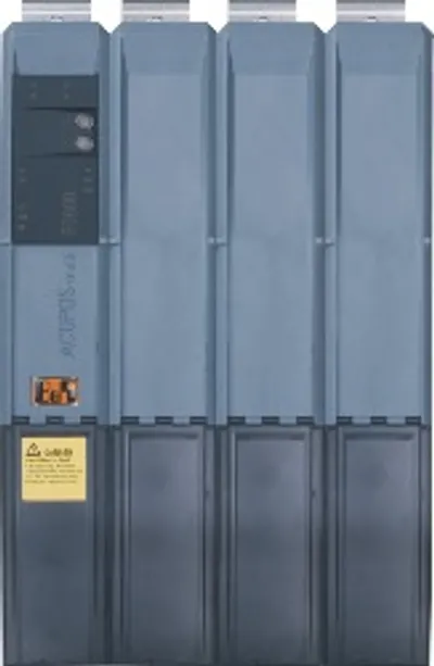
ACOPOSmulti3 power supply module, 88 A, AS
- MPN
- 8BVP0880HC00.008-3
Price and lead time confirmed within 1 business day
Request a Quote
- 12-month warranty (new) · 3-month (used/refurbished)
- 30-day returns, no restocking fee on unused parts
- Ships via



- 100% positive eBay feedback
What is the B&R 8BVP0880HC00.008-3?
ACOPOSmulti3 power supply module, 88 A, AS, cold plate or pass-through mounting, optimized for applications with decentralized, computationally intensive open-loop and closed-loop control requirements
Specifications
General information
| System requirements – Automation Studio | 4.6.1.x or later |
| Support – Dynamic node allocation (DNA) | Yes |
| Certifications – CE | Yes |
| Certifications – UKCA | Yes |
| Certifications – CRA (Cyber Resilience Act) | In preparation |
| Certifications – UL | cULus E225616; Power conversion equipment |
| Certifications – KC | Yes |
| B&R ID code | 0x2EE7 |
| Cooling and mounting type | Cold plate or pass-through mounting |
| Slots for plug-in modules | 2 |
Mains connection
| Max. chargeable DC bus capacitance depending on mains voltage – 230 VAC | 34.8 mF |
| Max. chargeable DC bus capacitance depending on mains voltage – 400 VAC | 11.5 mF |
| Max. chargeable DC bus capacitance depending on mains voltage – 480 VAC | 8 mF |
| Variant – L1, L2, L3, PE | M8 threaded bolts |
| Variant – Shield connection | Yes (note: Cables do not have to be shielded up to a total wiring length of 3 m between the line filter, regeneration choke and power supply module. Consult B&R when using cable lengths >3 m.) |
| Connection cross section range – Flexible and fine-stranded wires | ---) threaded bolts. The nominal cross section of the cable lug must match the cross section of the conductor to be connected in the particular application."> (note: The connection is made with cable lugs for M8 (0.32) |
| Network configurations | TT, TN-S, TN-C-SDelta/Wye with grounded wye neutral" in the USA."> (note: TT and TN power systems are commonly referred to as) |
| Mains input voltage | 3x 220 to 3x 480 VAC ±10% |
| Frequency | 50 / 60 Hz ±4% |
| Total harmonic distortion current (THDi) | <0.2% |
| Total harmonic distortion voltage (THDu) | <1% |
| Installed load | Max. 62 kW (note: The specified value already includes the power dissipation of the associated 8BVF line filter and associated 8BVR regeneration choke.) |
| Inrush current at 400 VAC | Max. 133 A |
| Switch-on interval | >300 s (note: At max. chargeable DC bus capacitance.) |
| Nominal switching frequency | 5 kHz |
| Possible switching frequencies | 5 / 10 kHz (note: B&R recommends operating the module at its nominal switching frequency. Operating the module at a higher switching frequency for application-specific reasons reduces the continuous power and increases CPU utilization.) |
| Integrated line filter per EN 61800-3, category C3 | No (note: Limit values from EN 61800-3 C3 (second environment).) |
| Integrated regeneration choke | No |
| Regenerative | Yes |
| Power factor correction (PFC) | Yes |
| Line fuse | Max. 264 A (gG fuses per IEC 60269-1 or Class CC, J, T); Max. 220 A (circuit breaker per EN 60947-2 or UL 489) |
| Terminal cable cross section dimension of shield connection | 32 to 50 mm |
DC bus connection
| Voltage – Nominal | 750 VDC |
| Reduction of continuous power depending on mains input voltage – Mains input voltage <3x 400 VAC | 150 W/V * (400 V - Mains input voltage) |
| Reduction of continuous power depending on DC bus voltage (U DC ) – U DC <750 VDC | 0.08 kW/V (note: P ... Actual continuous power available (value adapted to actual ambient conditions)) |
| Reduction of continuous power depending on switching frequency and mounting type – Cold plate mounting | 1.3 kW/K (starting at 58°C) (note: Valid under the following conditions: 750 VDC DC bus voltage, minimum permissible coolant flow volume (3 l/min).) |
| Reduction of continuous power depending on switching frequency and mounting type – Pass-through mounting | In preparation (note: Valid under the following conditions: 750 VDC DC bus voltage, minimum permissible coolant flow volume (3 l/min).) |
| Reduction of continuous power depending on switching frequency and mounting type – Cold plate mounting | 0.95 kW/K (starting at 27°C) (note: Valid under the following conditions: 750 VDC DC bus voltage, minimum permissible coolant flow volume (3 l/min).) |
| Reduction of continuous power depending on switching frequency and mounting type – Pass-through mounting | In preparation (note: Valid under the following conditions: 750 VDC DC bus voltage, minimum permissible coolant flow volume (3 l/min).) |
| Reduction of continuous power depending on installation elevation – Starting at 500 m above sea level | 6 kW per 1000 m |
| Reduction of peak power depending on mains input voltage – Mains input voltage <3x 400 VAC | 300 W/V * (400 V - Mains input voltage) |
| Power dissipation depending on switching frequency – Switching frequency 5 kHz | In preparation (note: Valid for a mains input voltage of 400 VAC and a DC bus voltage of 750 VDC. P ... Continuous power [kW].) |
| Power dissipation depending on switching frequency – Switching frequency 10 kHz | In preparation (note: Valid for a mains input voltage of 400 VAC and a DC bus voltage of 750 VDC. P ... Continuous power [kW].) |
| Protective measures – Overload protection | Yes |
| Protective measures – Short-circuit and ground fault protection | No |
| Continuous power (supply and regeneration) | 60 kW (note: Valid under the following conditions: Mains input voltage 3x 400 VAC, nominal DC bus voltage 750 VDC, switching frequency 5 kHz, 40°C ambient temperature, installation elevation <500 m above sea level, no derating due to cooling type.) |
| Peak power (supply and regeneration) | 120 kW |
| DC bus capacitance | 1650 µF |
| Variant | ACOPOSmulti backplane |
24 VDC power supply
| Input voltage | 25 VDC ±1.6% |
| Input capacitance | 4.7 µF |
| Max. power consumption | 27 W + P SLOT1 + P SLOT2 + P 24 V Out + P Fan8BVF... |
| Variant | ACOPOSmulti backplane |
24 VDC Out
| Output voltage – DC bus voltage (U DC ): 260 to 315 VDC | 25 VDC * (U DC / 315) |
| Output voltage – DC bus voltage (U DC ): 315 to 800 VDC | 24 VDC ±6% |
| Quantity | 2 |
| Fuse protection | 250 mA (slow-blow) electronic, automatic reset |
Filter fan connection
| Protective measures – Overload protection | No |
| Protective measures – Short-circuit proof | Yes |
| Protective measures – Open-circuit monitoring | No |
| Protective measures – Undervoltage monitoring | No |
| Output voltage | 24 V +5.8% / -0.1% |
| Continuous current | 4.2 A |
| Max. overcurrent limiting | 10 A |
Trigger inputs
| Electrical isolation – Input - Power supply module | Yes |
| Electrical isolation – Input - Input | Yes |
| Input voltage – Nominal | 24 VDC |
| Input voltage – Maximum | 30 VDC |
| Switching threshold – Low | <5 V |
| Switching threshold – High | >15 V |
| Switching delay – Rising edge | 52 μs ±0.5 μs (digitally filtered) |
| Switching delay – Falling edge | 53 μs ±0.5 μs (digitally filtered) |
| Quantity | 2 |
| Circuit | Sink |
| Input current at nominal voltage | Approx. 10 mA |
| Modulation compared to ground potential | Max. ±38 V |
Support
| Motion system – mapp Motion | 5.24.1 and higher |
| Motion system – ACP10/ARNC0 | 5.24.1 and higher |
Electrical properties
| Energy efficiency (IE classification) – Power dissipation relative to continuous apparent power | IE2 (10,25) 0.3%; IE2 (50,25) 0.3%; IE2 (10,50) 0.3%; IE2 (50,50) 0.6%; IE2 (90,50) 1.1%; IE2 (10,100) 0.3%; IE2 (50,100) 1.1%; IE2 (90,100) 2.3% |
| Energy efficiency (IE classification) – Nominal losses in standby mode | 11.8 W |
| Discharge capacitance | 0.9 µF |
Operating conditions
| Permissible mounting orientations – Hanging vertically | Yes |
| Permissible mounting orientations – Horizontal, face up | Yes |
| Permissible mounting orientations – Standing horizontally | No |
| Installation elevation above sea level – Nominal | 0 to 500 m |
| Installation elevation above sea level – Maximum | 4000 m (note: Continuous operation at an installation elevation of 500 m to 4,000 m above sea level is possible taking the specified reduction of continuous current into account. Requirements that go beyond this must be arranged with B&R.) |
| Pollution degree per EN 61800-5-1 | 2 (non-conductive pollution) |
| Overvoltage category per EN 61800-5-1 | III |
| Degree of protection per EN 60529 | IP20 |
Ambient conditions
| Temperature – Nominal | 5 to 40°C |
| Temperature – Maximum | 55°C |
| Temperature – Storage | -25 to 55°C |
| Temperature – Transport | -25 to 70°C |
| Relative humidity – Operation | 5 to 85% |
| Relative humidity – Storage | 5 to 95% |
| Relative humidity – Transport | Max. 95% at 40°C |
Mechanical properties
| Dimensions – Cold plate | 212 mm (note: These dimensions refer to the actual device dimensions including the respective mounting plate. Additional spacing above and below the devices must be taken into account for mounting, connections and air circulation.) |
| Dimensions – Pass-through mounting | 209 mm (note: These dimensions refer to the actual device dimensions including the respective mounting plate. Additional spacing above and below the devices must be taken into account for mounting, connections and air circulation.) |
| Dimensions – Width | 213.5 mm (note: These dimensions refer to the actual device dimensions including the respective mounting plate. Additional spacing above and below the devices must be taken into account for mounting, connections and air circulation.) |
| Dimensions – Height | 317 mm (note: These dimensions refer to the actual device dimensions including the respective mounting plate. Additional spacing above and below the devices must be taken into account for mounting, connections and air circulation.) |
| Weight | Approx. 8.4 kg |
| Module width | 4 |
Accessories
Required accessories (order separately)
| 8BZVP165000.000-1A | Terminal block sets — Screw clamp terminal block set for ACOPOSmulti 8BVP0880Hx00 and 8BVP1650Hx00 modules: 1x 8TB2104.204A-00, 1x 8TB2106.2010-00, 1x 8TB2108.20… |
Optional accessories (30)
| 8BXB000.0000-00 | Accessory sets — ACOPOSmulti accessory set for encoder buffering consisting of: 1x battery AA 3.6 V, 1x protective cover for battery holder |
| 8BXF001.0000-00 | Fan modules — ACOPOSmulti fan module, replacement fan for ACOPOSmulti modules (8BxP/8B0C/8BVI/8BVE/8B0K) |
| X20CA0E61.00100 | POWERLINK/Ethernet cables — POWERLINK/Ethernet connection cable, RJ45 to RJ45, 1 m |
| X20CA0E61.00050 | POWERLINK/Ethernet cables — POWERLINK/Ethernet connection cable, RJ45 to RJ45, 0.5 m |
| X20CA0E61.00035 | POWERLINK/Ethernet cables — POWERLINK/Ethernet connection cable, RJ45 to RJ45, 0.35 m |
| X20CA0E61.00030 | POWERLINK/Ethernet cables — POWERLINK/Ethernet connection cable, RJ45 to RJ45, 0.3 m |
| X20CA0E61.00025 | POWERLINK/Ethernet cables — POWERLINK/Ethernet connection cable, RJ45 to RJ45, 0.25 m |
| X20CA0E61.00020 | POWERLINK/Ethernet cables — POWERLINK/Ethernet connection cable, RJ45 to RJ45, 0.2 m |
| 8BAC0133.000-1 | Plug-in modules — Encoder emulation module for installation in ACOPOSmulti modules; 3 RS422 outputs; ABR encoder emulation ACOPOSmulti plug-in module, 3 RS42… |
| 8BAC0132.000-1 | Plug-in modules — Analog input module for installation in ACOPOSmulti modules; 4 high-speed analog inputs ±10 V ACOPOSmulti plug-in module, 4 analog inputs ±… |
| 8BAC0130.001-1 | Plug-in modules — Digital output module for installation in ACOPOSmulti modules; 2 high-speed outputs, +24 VDC; 2 standard readable outputs, +24 VDC ACOPOSmu… |
| 8BAC0130.000-1 | Plug-in modules — Digital mixed module for installation in ACOPOSmulti modules; 2 inputs, +24 VDC; 2 high-speed outputs, +24 VDC; 2 standard readable outputs… |
| 8BAC0125.000-1 | Plug-in modules — Interface for evaluating sinusoidal output signals; Functions and protocols selected through configuration (using a higher-level controller… |
| 8BAC0124.000-1 | Plug-in modules — SinCos interface for installation in ACOPOSmulti modules; Evaluation of incremental encoders with sinusoidal output signal; Encoder supply… |
| 8BAC0123.002-1 | Plug-in modules — Incremental encoder interface for installation in ACOPOSmulti modules; Evaluation of incremental encoders with push, pull or push-pull outp… |
| 8BAC0123.001-1 | Plug-in modules — Incremental encoder interface for installation in ACOPOSmulti modules; Evaluation of incremental encoders with push, pull or push-pull outp… |
| 8BAC0123.000-1 | Plug-in modules — Incremental encoder and SSI absolute encoder interface for installation in ACOPOSmulti modules; Evaluation of incremental/SSI encoders with… |
| 8BAC0122.000-1 | Plug-in modules — Resolver interface for installation in ACOPOSmulti modules; Encoder monitoring; High resolution ACOPOSmulti plug-in module, resolver interf… |
| 8BAC0121.000-1 | Plug-in modules — HIPERFACE interface for installation in ACOPOSmulti modules; Encoder monitoring; High resolution ACOPOSmulti plug-in module, HIPERFACE inte… |
| 8BAC0120.001-2 | Plug-in modules — EnDat 2.2 encoder interface for installation in ACOPOSmulti modules; Encoder monitoring; Embedded parameter chip when used with B&R motors… |
| 8BAC0120.000-1 | Plug-in modules — EnDat 2.1 encoder interface for installation in ACOPOSmulti modules; Encoder monitoring; High-precision analog signal processing; Embedded… |
| 8SCS010.0000-00 | Shield component sets — ACOPOSmulti shield component set: 1x ACOPOSmulti holding plate SK14-20, 1x shield connection clamp SK20 |
| 8SCS005.0000-00 | Shield component sets — ACOPOSmulti shield component set: 1x slot cover / shield plate |
| 8SCS004.0000-00 | Shield component sets — ACOPOSmulti shield component set: 1x shield plate 4x type 0, 2x hose clamps, B 9 mm, D 32-50 mm |
| 8SCS003.0000-00 | Shield component sets — ACOPOSmulti shield component set: 1x shield mounting plate 4x 45°, 8x screws |
| 8SCS002.0000-00 | Shield component sets — ACOPOSmulti shield component set: 1x clamping plate, 2x clamp D 4-13.5 mm, 2x screws |
| 8SCS001.0000-00 | Shield component sets — ACOPOSmulti shield component set: 1x shield plate 4x type 1, 1x hose clamp, B 9 mm, D 12-22 mm |
| 8TB2108.2010-00 | Terminal blocks — 8-pin screw clamp terminal block, 1-row, pitch: 5.08 mm, label 1: Numbered consecutively |
| 8TB2106.2010-00 | Terminal blocks — 6-pin screw clamp terminal block, 1-row, pitch: 5.08 mm, label 1: Numbered consecutively |
| 8TB2104.204A-00 | Terminal blocks — 4-pin screw clamp terminal block, 1-row, pitch: 5.08 mm, label 4: T- T+ F- F+, coding A: 0000 |
Downloads & documentation
Official documents from B&R, downloaded directly from the manufacturer.
Data sheets & manuals
CAD & dimension drawings
Certificates (1)
8BVP0880HC00.008-3: frequently asked questions
When can 8BVP0880HC00.008-3 be shipped?
8BVP0880HC00.008-3 is sourced on request — request a quote and we'll confirm the exact availability and shipping timeline for this specific unit.
Can I pick up 8BVP0880HC00.008-3 in person?
Local pickup from our Groningen, Netherlands warehouse may be possible — contact us before ordering to check availability and arrange a collection time.
Is express delivery available?
Yes — mention it when you request a quote for 8BVP0880HC00.008-3 and we'll include express shipping options in our reply.
My factory is down and I need this urgently — can you help?
For a critical breakdown, contact us directly at +31 (0)50-7110348 or sales@partnerplc.com — we can look into same-day courier or dedicated taxi/hotshot delivery for 8BVP0880HC00.008-3, subject to availability and destination.
More B&R parts
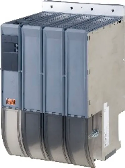
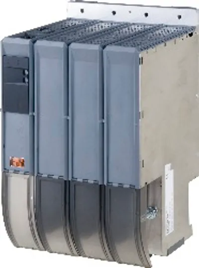
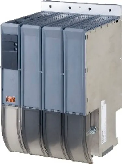
B&R 8BVP0880HC00.008-3Price and lead time confirmed within 1 business day
Request a Quote