























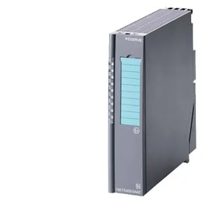
Siemens 6ES7136-6CB00-0CA0
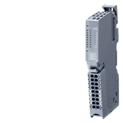
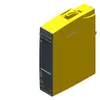
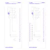
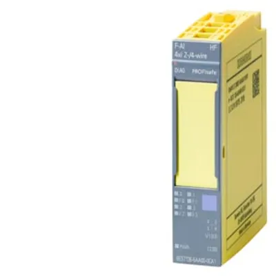
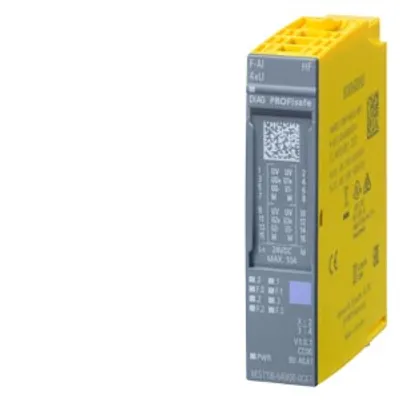
SIMATIC ET 200SP, F-TM Count 1x1Vpp sin/cos HF, PROFIsafe, 1 channel, for incremental rotary encoders
- MPN
- 6ES7136-6CB00-0CA0
- Category
- Fail-safe technology modules
Price and lead time confirmed within 1 business day
Request a Quote
- 12-month warranty (new) · 3-month (used/refurbished)
- 30-day returns, no restocking fee on unused parts
- Ships via



- 100% positive eBay feedback
What is the Siemens 6ES7136-6CB00-0CA0?
SIMATIC ET 200SP, F-TM Count 1x1Vpp sin/cos HF, PROFIsafe, 1 channel, for incremental rotary encoders, sin/cos 1 Vpp, suitable for BU type A0, pack quantity: 1 unit
Specifications
General information
| Product type designation | F-TM Count 1x1Vpp sin/cos HF |
| Firmware version | V1.0 |
| Firmware version — FW update possible | Yes |
| usable BaseUnits | BU type A0 |
| Color code for module-specific color-coded label | CC01 |
| Product function — I&M data | Yes; I&M0 to I&M3 |
| Engineering with — STEP 7 TIA Portal configurable/integrated from version | Step 7 V17 or higher: use GSDML for prior versions |
Supply voltage
| Rated value (DC) | 24 V |
| power supply according to NEC Class 2 required | No |
| Load voltage L+ — Rated value (DC) | 24 V |
| Load voltage L+ — permissible range, lower limit (DC) | 20.4 V |
| Load voltage L+ — permissible range, upper limit (DC) | 28.8 V |
| Load voltage L+ — Reverse polarity protection | Yes |
Input current
| Current consumption, max. | 50 mA; without load, 150 mA with 300 mA encoder load |
Encoder supply
| 5 V encoder supply — 5 V | Yes; 5.1 V ±3.5 % |
| 5 V encoder supply — Short-circuit protection | Yes; Electronic overload protection; no protection on applying a normal or counter voltage. |
| 5 V encoder supply — Output current, max. | 300 mA |
Power loss
| Power loss, typ. | 1.25 W |
Address area
| Address space per module — Inputs | 14 byte; S7-300/400F CPU, 13 byte |
| Address space per module — Outputs | 5 byte; S7-300/400F CPU, 4 byte |
Hardware configuration
| Automatic encoding | Yes |
| Automatic encoding — Electronic coding element type H | Yes |
Digital inputs
| Number of digital inputs | 1; (counter input) |
| Digital inputs, parameterizable | Yes |
| Digital input functions, parameterizable — Gate start/stop | Yes |
| Digital input functions, parameterizable — Counter for incremental encoder | Yes |
| Digital input functions, parameterizable — Counter for incremental encoder — Number, max. | 1 |
| Input voltage — Type of input voltage | sin/cos 1 Vpp |
| Input delay (for rated value of input voltage) — Minimum pulse width for program reactions | 2.5 µs |
| Input delay (for rated value of input voltage) — for technological functions — Parameterizable | Yes |
| Cable length — shielded, max. | 150 m |
Encoder
| Connectable encoders — Incremental encoder (symmetrical) | Yes; up to 200 kHz depending on cable type and length |
| Encoder signals, incremental encoder (symmetrical) — Input voltage | 1 Vpp, centered at 2.5 V offset |
| Encoder signals, incremental encoder (symmetrical) — Input frequency, max. | 200 kHz |
| Encoder signals, incremental encoder (symmetrical) — Counting frequency, max. | 800 kHz; with quadruple evaluation |
| Encoder signals, incremental encoder (symmetrical) — Cable length, shielded, max. | 150 m |
| Encoder signals, incremental encoder (symmetrical) — Incremental encoder with A/B tracks, 90° phase offset | Yes; sin/cos |
| Encoder signals, incremental encoder (symmetrical) — Incremental encoder with A/B tracks, 90° phase offset and zero track | Yes; sin/cos/zero |
Interfaces
| Number of RS 485 interfaces | 0 |
Interrupts/diagnostics/status information
| Diagnostics function | Yes; see chapter "Diagnostic Messages" in the manual |
| Alarms — Diagnostic alarm | Yes |
| Alarms — Hardware interrupt | No |
| Diagnoses — Monitoring the supply voltage | Yes |
| Diagnoses — Wire break | Yes |
| Diagnoses — short-circuit | Yes |
| Diagnoses — A/B transition error at incremental encoder | Yes |
| Diagnostics indication LED — RUN LED | Yes; green LED |
| Diagnostics indication LED — ERROR LED | Yes; red LED |
| Diagnostics indication LED — Monitoring of the supply voltage (PWR-LED) | Yes; green LED |
| Diagnostics indication LED — Channel status display | Yes; green LED |
| Diagnostics indication LED — for channel diagnostics | Yes; red LED |
| Diagnostics indication LED — for module diagnostics | Yes; green/red DIAG LED |
Integrated Functions
| Counter | Yes |
| Counter — Number of counters | 1 |
| Counter — Counting frequency, max. | 800 kHz; with quadruple evaluation |
| Safety monitoring functions — Safe Operating Stop (SOS) | Yes |
| Safety monitoring functions — Safely-Limited Speed (SLS) | Yes |
| Safety monitoring functions — Safe Direction (SDI) | Yes |
| Safety monitoring functions — Safe Speed Monitor (SSM) | Yes |
| Counting functions — Continuous counting | Yes |
| Counting functions — Counter response parameterizable | Yes |
| Counting functions — Software gate | Yes |
| Counting functions — Counting range, parameterizable | Yes |
| Measuring functions — Measuring range — Frequency measurement, min. | 0.04 Hz |
| Measuring functions — Measuring range — Frequency measurement, max. | 800 kHz; with quadruple evaluation |
| Measuring functions — Measuring range — Cycle duration measurement, min. | 1 µs |
| Measuring functions — Measuring range — Cycle duration measurement, max. | 25 s |
| Measuring functions — Measuring range — Velocity measurement, min. | 0 (speed in configured units per selected time basis - speed*1 000) |
| Measuring functions — Measuring range — Velocity measurement, max. | 2 147 483 (speed in configured units per selected time basis - speed*1 000) |
| Measuring functions — Accuracy — Frequency measurement | up to 100 ppm; depending on measuring interval and signal evaluation; at low frequency external noise may have an effect on accuracy (reference the graph in 2.2.3) |
| Measuring functions — Accuracy — Cycle duration measurement | up to 100 ppm; depending on measuring interval and signal evaluation; at low frequency external noise may have an effect on accuracy (reference the graph in 2.2.3) |
| Measuring functions — Accuracy — Velocity measurement | up to 100 ppm; depending on measuring interval and signal evaluation; at low frequency external noise may have an effect on accuracy (reference the graph in 2.2.3) |
Potential separation
| Potential separation channels — between the channels | No; Only one channel is available |
| Potential separation channels — between the channels and backplane bus | Yes |
| Potential separation channels — Between the channels and load voltage L+ | No |
| Potential separation channels — between the channels and the power supply of the electronics | No |
Isolation
| Isolation tested with | 707 V DC (type test) |
Standards, approvals, certificates
| Suitable for safety functions | Yes |
| Ecological footprint — environmental product declaration | Yes |
| Ecological footprint — Global warming potential — global warming potential, (total) [CO2 eq] | 88.3 kg |
| Ecological footprint — Global warming potential — global warming potential, (during production) [CO2 eq] | 13.1 kg |
| Ecological footprint — Global warming potential — global warming potential, (during operation) [CO2 eq] | 76.6 kg |
| Ecological footprint — Global warming potential — global warming potential, (after end of life cycle) [CO2 eq] | -1.37 kg |
| Highest safety class achievable in safety mode — Performance level according to ISO 13849-1 | Cat. 4, PLe |
| Highest safety class achievable in safety mode — SIL acc. to IEC 61508 | SIL 3 |
| Highest safety class achievable in safety mode — Probability of failure (for service life of 20 years and repair time of 100 hours) — low demand mode: PFDavg in accordance with SIL1 | < 2.00E-03 signal monitoring disabled |
| Highest safety class achievable in safety mode — Probability of failure (for service life of 20 years and repair time of 100 hours) — Low demand mode: PFDavg in accordance with SIL3 | < 3.00E-05 |
| Highest safety class achievable in safety mode — Probability of failure (for service life of 20 years and repair time of 100 hours) — high demand/continuous mode: PFH in accordance with SIL1 | < 3.00E-08 1/h signal monitoring disabled |
| Highest safety class achievable in safety mode — Probability of failure (for service life of 20 years and repair time of 100 hours) — High demand/continuous mode: PFH in accordance with SIL3 | < 1.00E-09 1/h |
Ambient conditions
| Ambient temperature during operation — horizontal installation, min. | 0 °C |
| Ambient temperature during operation — horizontal installation, max. | 60 °C |
| Ambient temperature during operation — vertical installation, min. | 0 °C |
| Ambient temperature during operation — vertical installation, max. | 55 °C |
| Altitude during operation relating to sea level — Ambient air temperature-barometric pressure-altitude | On request: Installation altitudes greater than 2 000 m |
Dimensions
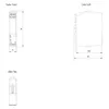
| Width | 15 mm |
| Height | 73 mm |
| Depth | 58 mm |
Weights
| Weight, approx. | 42 g |
Downloads & documentation
Official documents from Siemens, downloaded directly from the manufacturer.
Data sheets & manuals
6ES7136-6CB00-0CA0: frequently asked questions
When can 6ES7136-6CB00-0CA0 be shipped?
6ES7136-6CB00-0CA0 is sourced on request — request a quote and we'll confirm the exact availability and shipping timeline for this specific unit.
Can I pick up 6ES7136-6CB00-0CA0 in person?
Local pickup from our Groningen, Netherlands warehouse may be possible — contact us before ordering to check availability and arrange a collection time.
Is express delivery available?
Yes — mention it when you request a quote for 6ES7136-6CB00-0CA0 and we'll include express shipping options in our reply.
My factory is down and I need this urgently — can you help?
For a critical breakdown, contact us directly at +31 (0)50-7110348 or sales@partnerplc.com — we can look into same-day courier or dedicated taxi/hotshot delivery for 6ES7136-6CB00-0CA0, subject to availability and destination.
More Siemens parts
Siemens 6ES7136-6CB00-0CA0Price and lead time confirmed within 1 business day
Request a Quote