























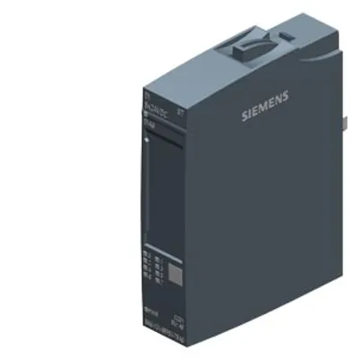
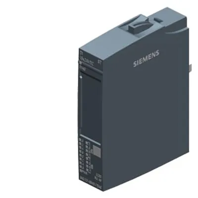
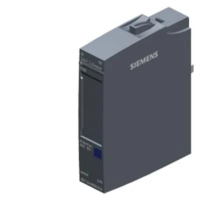
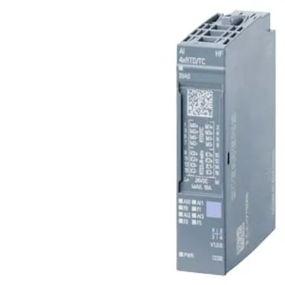
Siemens 6AG1131-6TF00-7CA0
SIPLUS ET 200SP DI 8xNAMUR HF based on 6ES7131-6TF00-0CA0 with conformal coating, -40…+70 °C
- MPN
- 6AG1131-6TF00-7CA0
- Category
- SIPLUS digital inputs
Price and lead time confirmed within 1 business day
Request a Quote
- 12-month warranty (new) · 3-month (used/refurbished)
- 30-day returns, no restocking fee on unused parts
- Ships via



- 100% positive eBay feedback
What is the Siemens 6AG1131-6TF00-7CA0?
SIPLUS ET 200SP DI 8xNAMUR HF based on 6ES7131-6TF00-0CA0 with conformal coating, -40…+70 °C, digital input module, suitable for BU type A0, color code CC01, channel diagnostics
Specifications
General information
| Product type designation | DI 8xNAMUR HF |
| Firmware version — FW update possible | Yes |
| based on | 6ES7131-6TF00-0CA0 |
| usable BaseUnits | BU type A0 |
| Color code for module-specific color-coded label | CC01 |
| Product function — I&M data | Yes; I&M0 to I&M3 |
| Product function — Isochronous mode | No |
| Product function — suitable for operation on PROFINET R1 IMs | Yes |
| Engineering with — STEP 7 TIA Portal configurable/integrated from version | see entry ID: 109746275 |
| Operating mode — DI | Yes |
| Operating mode — Counter | Yes |
| Operating mode — Oversampling | No |
| Operating mode — MSI | No |
Supply voltage
| Rated value (DC) | 24 V |
| permissible range, lower limit (DC) | 19.2 V |
| permissible range, upper limit (DC) | 28.8 V |
| Reverse polarity protection | Yes |
Input current
| Current consumption, max. | 70 mA |
Encoder supply
| Number of outputs | 8 |
| Short-circuit protection | Yes |
| 24 V encoder supply — 24 V | No |
| 24 V encoder supply — Short-circuit protection | No |
| NAMUR encoder supply — 8.2 V | Yes |
| NAMUR encoder supply — Short-circuit protection | Yes |
| NAMUR encoder supply — Output current per channel, max. | 8 mA |
| NAMUR encoder supply — Output current per module, max. | 64 mA |
Power loss
| Power loss, typ. | 1.5 W |
Address area
| Address space per module — Address space per module, max. | 1 byte |
| Address space per module — Inputs | 42 byte; 1 byte + 1 byte for QI information in DI mode; 42 bytes in Counter mode |
| Address space per module — Outputs | 20 byte; 0 in DI mode; 20 bytes in Counter mode |
Hardware configuration
| Automatic encoding | Yes |
| Automatic encoding — Mechanical coding element | Yes |
| Automatic encoding — Type of mechanical coding element | Type A |
| Submodules — Number of configurable submodules, max. | 1 |
| Selection of BaseUnit for connection variants — 2-wire connection | BU type A0 |
| Selection of BaseUnit for connection variants — 3-wire connection | BU type A0 |
Digital inputs
| Number of digital inputs | 8; NAMUR |
| Digital inputs, parameterizable | Yes |
| Sourcing/sinking input | P-reading |
| Pulse extension | Yes; 0.5 s, 1 s, 2 s |
| Edge evaluation | Yes; rising edge, falling edge, edge change |
| Signal change flutter | Yes; 2 to 32 signal changes |
| Flutter observation window | Yes; 0.5 s, 1 s to 100 s in 1-s steps |
| Digital input functions, parameterizable — Gate start/stop | Yes |
| Digital input functions, parameterizable — Freely usable digital input | Yes |
| Digital input functions, parameterizable — Counter | Yes |
| Digital input functions, parameterizable — Counter — Number, max. | 4; See manual for details |
| Digital input functions, parameterizable — Counter — Counting frequency, max. | 5 kHz |
| Digital input functions, parameterizable — Counter — Counting width | 32 bit |
| Digital input functions, parameterizable — Counter — Counting direction up/down | Yes |
| Input voltage — Rated value (DC) | 8.2 V |
| Input current — for 10 k switched contact — for signal "0", min. | 0.35 mA |
| Input current — for 10 k switched contact — for signal "0", max. | 1.2 mA |
| Input current — for 10 k switched contact — for signal "1", min. | 2.1 mA |
| Input current — for 10 k switched contact — for signal "1", max. | 7 mA |
| Input current — for unswitched contact — for signal "0", max. (permissible quiescent current) | 0.5 mA |
| Input current — for unswitched contact — for signal "1", typ. | 8 mA |
| Input current — for NAMUR encoders — for signal "0", min. | 0.35 mA |
| Input current — for NAMUR encoders — for signal "0", max. | 1.2 mA |
| Input current — for NAMUR encoders — for signal "1", min. | 2.1 mA |
| Input current — for NAMUR encoders — for signal "1", max. | 7 mA |
| Input delay (for rated value of input voltage) — tolerated changeover time for changeover contacts | 300 ms |
| Input delay (for rated value of input voltage) — for standard inputs — Parameterizable | No |
| Input delay (for rated value of input voltage) — for NAMUR inputs — at "0" to "1", max. | 20 ms; See manual for details |
| Input delay (for rated value of input voltage) — for NAMUR inputs — at "1" to "0", max. | 20 ms; See manual for details |
| Cable length — shielded, max. | 200 m; 50 m for Counter mode |
Encoder
| Connectable encoders — NAMUR encoder/changeover contact according to EN 60947 | Yes |
| Connectable encoders — Single contact / changeover contact unconnected | Yes |
| Connectable encoders — Single contact / changeover contact connected with 10 kΩ | Yes |
Interrupts/diagnostics/status information
| Diagnostics function | Yes |
| Alarms — Diagnostic alarm | Yes; channel by channel |
| Alarms — Hardware interrupt | Yes; Parameterizable, channels 0 to 7 |
| Diagnoses — Diagnostic information readable | Yes |
| Diagnoses — Monitoring the supply voltage | Yes |
| Diagnoses — Monitoring the supply voltage — parameterizable | Yes |
| Diagnoses — Monitoring of encoder power supply | No |
| Diagnoses — Wire break | Yes; channel by channel |
| Diagnoses — Short-circuit | Yes; channel by channel |
| Diagnostics indication LED — Monitoring of the supply voltage (PWR-LED) | Yes; green PWR LED |
| Diagnostics indication LED — Channel status display | Yes; green LED |
| Diagnostics indication LED — for channel diagnostics | Yes; red LED |
| Diagnostics indication LED — for module diagnostics | Yes; green/red DIAG LED |
Potential separation
| Potential separation channels — between the channels | No |
| Potential separation channels — between the channels and backplane bus | Yes |
| Potential separation channels — Between the channels and load voltage L+ | Yes |
| Potential separation channels — between the channels and the power supply of the electronics | Yes |
Isolation
| Isolation tested with | 707 V DC (type test) |
Standards, approvals, certificates
| Suitable for safety functions | No |
Ambient conditions
| Ambient temperature during operation — horizontal installation, min. | -40 °C; = Tmin (incl. condensation/frost); start-up @ -25 °C |
| Ambient temperature during operation — horizontal installation, max. | 70 °C; = Tmax; > +60 °C number of simultaneously controllable inputs max. 4 (no adjacent points) |
| Ambient temperature during operation — vertical installation, min. | -40 °C; = Tmin |
| Ambient temperature during operation — vertical installation, max. | 50 °C; = Tmax |
| Altitude during operation relating to sea level — Installation altitude above sea level, max. | 5 000 m |
| Altitude during operation relating to sea level — Ambient air temperature-barometric pressure-altitude | Tmin ... Tmax at 1 140 hPa ... 795 hPa (-1 000 m ... +2 000 m) // Tmin ... (Tmax - 10 K) at 795 hPa ... 658 hPa (+2 000 m ... +3 500 m) // Tmin ... (Tmax -20 K) at 658 hPa ... 540 hPa (+3 500 m ... +5 000 m) |
| Relative humidity — With condensation, tested in accordance with IEC 60068-2-38, max. | 100 %; RH incl. condensation / frost (no commissioning in bedewed state), horizontal installation |
| Resistance — Coolants and lubricants — Resistant to commercially available coolants and lubricants | Yes; Incl. diesel and oil droplets in the air |
| Resistance — Use in stationary industrial systems — to biologically active substances according to EN 60721-3-3 | Yes; Class 3B2 mold, fungus and dry rot spores (with the exception of fauna); Class 3B3 on request |
| Resistance — Use in stationary industrial systems — to chemically active substances according to EN 60721-3-3 | Yes; Class 3C4 (RH < 75 %) incl. salt spray acc. to EN 60068-2-52 (severity degree 3); * |
| Resistance — Use in stationary industrial systems — to mechanically active substances according to EN 60721-3-3 | Yes; Class 3S4 incl. sand, dust, * |
| Resistance — Use in stationary industrial systems — Against mechanical environmental conditions acc. to EN 60721-3-3 | Yes; Class 3M8 using the SIPLUS Mounting Kit ET 200SP (6AG1193-6AA00-0AA0) |
| Resistance — Use on ships/at sea — to biologically active substances according to EN 60721-3-6 | Yes; Class 6B2 mold and fungal spores (excluding fauna); Class 6B3 on request |
| Resistance — Use on ships/at sea — to chemically active substances according to EN 60721-3-6 | Yes; Class 6C3 (RH < 75 %) incl. salt spray acc. to EN 60068-2-52 (severity degree 3); * |
| Resistance — Use on ships/at sea — to mechanically active substances according to EN 60721-3-6 | Yes; Class 6S3 incl. sand, dust; * |
| Resistance — Use on ships/at sea — Against mechanical environmental conditions acc. to EN 60721-3-6 | Yes; Class 6M4 using the SIPLUS Mounting Kit ET 200SP (6AG1193-6AA00-0AA0) |
| Resistance — Usage in industrial process technology — Against chemically active substances acc. to EN 60654-4 | Yes; Class 3 (excluding trichlorethylene) |
| Resistance — Usage in industrial process technology — Environmental conditions for process, measuring and control systems acc. to ANSI/ISA-71.04 | Yes; Level GX group A/B (excluding trichlorethylene; harmful gas concentrations up to the limits of EN 60721-3-3 class 3C4 permissible); level LC3 (salt spray) and level LB3 (oil) |
| Resistance — Remark — Note regarding classification of environmental conditions acc. to EN 60721, EN 60654-4 and ANSI/ISA-71.04 | * The supplied plug covers must remain in place over the unused interfaces during operation! |
| Conformal coating — Coatings for printed circuit board assemblies acc. to EN 61086 | Yes; Class 2 for high reliability |
| Conformal coating — Protection against fouling acc. to EN 60664-3 | Yes; Type 1 protection |
| Conformal coating — Military testing according to MIL-I-46058C, Amendment 7 | Yes; Discoloration of coating possible during service life |
| Conformal coating — Qualification and Performance of Electrical Insulating Compound for Printed Board Assemblies according to IPC-CC-830A | Yes; Conformal coating, Class A |
Dimensions
| Width | 15 mm |
| Height | 73 mm |
| Depth | 58 mm |
Weights
| Weight, approx. | 32 g |
Downloads & documentation
Official documents from Siemens, downloaded directly from the manufacturer.
Data sheets & manuals
6AG1131-6TF00-7CA0: frequently asked questions
When can 6AG1131-6TF00-7CA0 be shipped?
6AG1131-6TF00-7CA0 is sourced on request — request a quote and we'll confirm the exact availability and shipping timeline for this specific unit.
Can I pick up 6AG1131-6TF00-7CA0 in person?
Local pickup from our Groningen, Netherlands warehouse may be possible — contact us before ordering to check availability and arrange a collection time.
Is express delivery available?
Yes — mention it when you request a quote for 6AG1131-6TF00-7CA0 and we'll include express shipping options in our reply.
My factory is down and I need this urgently — can you help?
For a critical breakdown, contact us directly at +31 (0)50-7110348 or sales@partnerplc.com — we can look into same-day courier or dedicated taxi/hotshot delivery for 6AG1131-6TF00-7CA0, subject to availability and destination.
More Siemens parts
Siemens 6AG1131-6TF00-7CA0Price and lead time confirmed within 1 business day
Request a Quote