




.svg&w=240)


















FX5-20PG-D Mitsubishi MELSEC iQ-F Series Motion/positioning module
Request a Quote



Quick facts
| Availability | Confirmed on request |
| Category | Mitsubishi MELSEC iQ-F Series – Motion/Positioning Module |
| Lifecycle | Active |
| Warranty | 12-month (new) · 3-month (used/refurbished) |
Shipping & availability
When can FX5-20PG-D be shipped?
FX5-20PG-D is sourced on request — request a quote and we'll confirm the exact availability and shipping timeline for this specific unit.
Can I pick up FX5-20PG-D in person?
Local pickup from our Groningen, Netherlands warehouse may be possible — contact us before ordering to check availability and arrange a collection time.
Is express delivery available?
Yes — mention it when you request a quote for FX5-20PG-D and we'll include express shipping options in our reply.
My factory is down and I need this urgently — can you help?
For a critical breakdown, contact us directly at +31 (0)50-7110348 or sales@partnerplc.com — we can look into same-day courier or dedicated taxi/hotshot delivery for FX5-20PG-D, subject to availability and destination.
The Mitsubishi Electric FX5-20PG-D is a motion/positioning module in the MELSEC iQ-F Series. Pulse output: 2 axes (Differential driver output system). Specifications and manuals below are Mitsubishi Electric's own data.
Specifications
Product
| Series | MELSEC iQ-F Series |
| Category | Motion/positioning module |
| Outline | Pulse output: 2 axes (Differential driver output system) |
Specifications
| Applicable CPU module | FX5UJ CPU module: From the first FX5U CPU module: Ver. 1.050 or later FX5UC CPU module*: Ver. 1.050 or later * FX5-CNV-IFC or FX5-C1PS-5V is required to connect to the FX5UC CPU module. |
| Applicable engineering tool: GX Works3 | FX5UJ CPU module: Ver. 1.060N or later FX5U CPU module: Ver. 1.050C or later FX5UC CPU module: Ver. 1.050C or later |
| Number of occupied I/O points | 8 points |
| Mass (weight) | Approx. 0.2 kg |
| Number of control axes | 2 axes |
| Control system | PTP (Point-To-Point) control, path control (line and arc can be set), speed control, speed position switching control, position-speed switching control |
| Control unit | mm, inch, degree, pulse |
| Pulse output form | Differential driver |
| Interpolation function | 2-axis linear interpolation, 2-axis circular interpolation |
| Positioning data | 600 data/axis |
| Maximum connection distance between servos | 10 m |
| Number of write accesses to flash ROM | 100000 times maximum |
Power supply specifications
| External power supply: Power supply voltage | 24 V DC +20%, -15% |
| External power supply: Allowable instantaneous power failure time | Operation continues when the instantaneous power failure is shorter than 5 ms. |
| External power supply: Current consumption | 165 mA |
Input specifications
| Drive unit READY signal (READY), Stop signal (STOP), Upper limit signal (FLS), Lower limit signal (RLS): Signal voltage | 24 V DC |
| Drive unit READY signal (READY), Stop signal (STOP), Upper limit signal (FLS), Lower limit signal (RLS): Input current | 5 mA |
| Drive unit READY signal (READY), Stop signal (STOP), Upper limit signal (FLS), Lower limit signal (RLS): ON current | 3.5 mA or more |
| Drive unit READY signal (READY), Stop signal (STOP), Upper limit signal (FLS), Lower limit signal (RLS): OFF current | 1.7 mA or less |
| Drive unit READY signal (READY), Stop signal (STOP), Upper limit signal (FLS), Lower limit signal (RLS): Signal format | No-voltage contact input Sink: NPN open collector transistor Source: PNP open collector transistor |
| Drive unit READY signal (READY), Stop signal (STOP), Upper limit signal (FLS), Lower limit signal (RLS): Response time | 4 ms or less |
| Drive unit READY signal (READY), Stop signal (STOP), Upper limit signal (FLS), Lower limit signal (RLS): Insulation of circuit | Photo-coupler insulation |
| Drive unit READY signal (READY), Stop signal (STOP), Upper limit signal (FLS), Lower limit signal (RLS): Indication of operation | None (Operation check via buffer memory is possible.) |
| Zero signal (PG05/PG024): Signal voltage | PG05: 5 V DC PG024: 24 V DC |
| Zero signal (PG05/PG024): Input current | 5 mA |
| Zero signal (PG05/PG024): ON current | PG05: 2 mA or more PG024: 3 mA or more |
| Zero signal (PG05/PG024): OFF current | PG05: 0.5 mA or less PG024: 0.2 mA or less |
| Zero signal (PG05/PG024): Signal format | NPN open collector transistor |
| Zero signal (PG05/PG024): Response time | 1 ms or less |
| Zero signal (PG05/PG024): Insulation of circuit | Photo-coupler insulation |
| Zero signal (PG05/PG024): Indication of operation | None (Operation check via buffer memory is possible.) |
| Manual pulse generator phase A (PULSER A)/Manual pulse generator phase B (PULSER B): Signal voltage | 5 V DC |
| Manual pulse generator phase A (PULSER A)/Manual pulse generator phase B (PULSER B): Input current | 14 mA |
| Manual pulse generator phase A (PULSER A)/Manual pulse generator phase B (PULSER B): ON current | 2 mA or more |
| Manual pulse generator phase A (PULSER A)/Manual pulse generator phase B (PULSER B): OFF current | 0.2 mA or less |
| Manual pulse generator phase A (PULSER A)/Manual pulse generator phase B (PULSER B): Signal format | NPN open collector transistor |
| Manual pulse generator phase A (PULSER A)/Manual pulse generator phase B (PULSER B): Response frequency | 100 kHz |
| Manual pulse generator phase A (PULSER A)/Manual pulse generator phase B (PULSER B): Insulation of circuit | Photo-coupler insulation |
| Manual pulse generator phase A (PULSER A)/Manual pulse generator phase B (PULSER B): Indication of operation | None (Operation check via buffer memory is possible.) |
| Near-point dog signal (DOG): Signal voltage | 24 V DC |
| Near-point dog signal (DOG): Input current | 5 mA |
| Near-point dog signal (DOG): ON current | 3.5 mA or more |
| Near-point dog signal (DOG): OFF current | 1.7 mA or less |
| Near-point dog signal (DOG): Signal format | No-voltage contact input Sink: NPN open collector transistor Source: PNP open collector transistor |
| Near-point dog signal (DOG): Response time | 1 ms or less |
| Near-point dog signal (DOG): Insulation of circuit | Photo-coupler insulation |
| Near-point dog signal (DOG): Indication of operation | None (Operation check via buffer memory is possible.) |
| External command signal (CHG): Signal voltage | 24 V DC |
| External command signal (CHG): Input current | 5 mA |
| External command signal (CHG): ON current | 2.7 mA or more |
| External command signal (CHG): OFF current | 0.8 mA or less |
| External command signal (CHG): Signal format | No-voltage contact input Sink: NPN open collector transistor Source: PNP open collector transistor |
| External command signal (CHG): Response time | 20 μs |
| External command signal (CHG): Insulation of circuit | Photo-coupler insulation |
| External command signal (CHG): Indication of operation | None (Operation check via buffer memory is possible.) |
Output specifications
| Deviation counter clear signal (CLEAR): Pulse output form | Transistor |
| Deviation counter clear signal (CLEAR): Signal output time | 1 to 65535 ms |
| Deviation counter clear signal (CLEAR): Rated load voltage | 5 to 24 V DC |
| Deviation counter clear signal (CLEAR): Maximum load current | 100 mA |
| Deviation counter clear signal (CLEAR): Output ON voltage | 1.5 V or less |
| Deviation counter clear signal (CLEAR): Indication of operation | None (Operation check via buffer memory is possible.) |
| Pulse output (PULSE R+/PULSE F+) | Differential driver (equivalent to AM26C31) |
The general specifications other than below are the same as those for the CPU module.
| Dielectric withstand voltage: Between all external terminals and ground terminal of CPU module | 500 V AC for one minute |
| Insulation resistance: Between all external terminals and ground terminal of CPU module | 10 MΩ or higher by 500 V DC insulation resistance tester |
Downloads & documentation
Official documents from Mitsubishi Electric (Factory Automation), downloaded directly from the manufacturer.
Data sheets & manuals
More Mitsubishi Electric (Factory Automation) parts
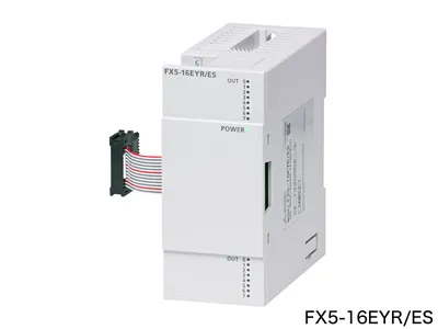 Available on requestFX5-16EYR/ES Mitsubishi MELSEC iQ-F Series Input/Output Module
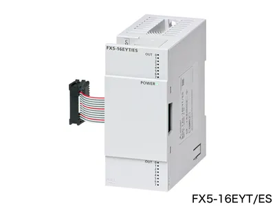 Available on requestFX5-16EYT/ES Mitsubishi MELSEC iQ-F Series Input/Output Module
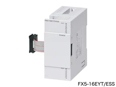 Available on requestFX5-16EYT/ESS Mitsubishi MELSEC iQ-F Series Input/Output Module
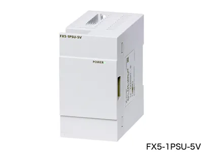 Available on requestFX5-1PSU-5V Mitsubishi MELSEC iQ-F Series Option
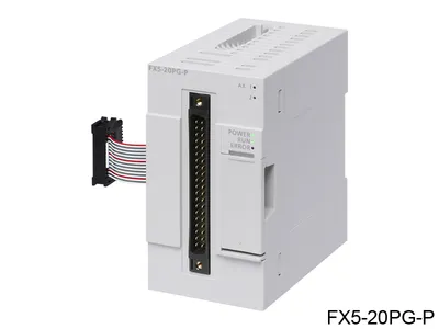 Available on requestFX5-20PG-P Mitsubishi MELSEC iQ-F Series Motion/positioning module
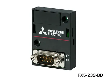 Available on requestFX5-232-BD Mitsubishi MELSEC iQ-F Series Network/communication module
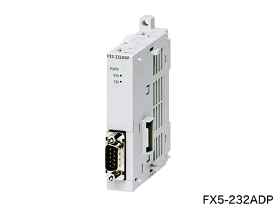 Available on requestFX5-232ADP Mitsubishi MELSEC iQ-F Series Network/communication module
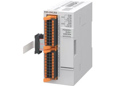 Available on requestFX5-2HC/ES Mitsubishi MELSEC iQ-F Series High-speed counter module