




.svg&w=240)


















FX2N-20GM Mitsubishi MELSEC-F (FX) Series Positioning
Discontinued by Mitsubishi Electric (Factory Automation) — we can still source the original FX2N-20GM (new, used or refurbished, subject to availability). Request a quote below.
Request a Quote



Quick facts
| Availability | Confirmed on request |
| Category | Mitsubishi MELSEC-F (FX) Series – Positioning |
| Lifecycle | Discontinued |
| Warranty | 12-month (new) · 3-month (used/refurbished) |
Shipping & availability
Can I still buy the FX2N-20GM now that it is discontinued?
Yes. Mitsubishi Electric (Factory Automation) has discontinued the FX2N-20GM, but sourcing discontinued parts is what PartnerPLC specialises in — new old stock, used and refurbished units. Request a quote and we'll confirm availability, condition and lead time.
When can FX2N-20GM be shipped?
FX2N-20GM is sourced on request — request a quote and we'll confirm the exact availability and shipping timeline for this specific unit.
Can I pick up FX2N-20GM in person?
Local pickup from our Groningen, Netherlands warehouse may be possible — contact us before ordering to check availability and arrange a collection time.
Is express delivery available?
Yes — mention it when you request a quote for FX2N-20GM and we'll include express shipping options in our reply.
My factory is down and I need this urgently — can you help?
For a critical breakdown, contact us directly at +31 (0)50-7110348 or sales@partnerplc.com — we can look into same-day courier or dedicated taxi/hotshot delivery for FX2N-20GM, subject to availability and destination.
The Mitsubishi Electric FX2N-20GM is a positioning in the MELSEC-F (FX) Series. Pulse output: 2-axes (independent/simultaneous). Mitsubishi Electric has discontinued it (2020/03 Discontinued); PartnerPLC sources discontinued Mitsubishi parts on the surplus market for maintenance of existing machines. Specifications and manuals below are Mitsubishi Electric's own data.
Specifications
Product
| Series | MELSEC-F (FX) Series |
| Category | Positioning |
| Sales status | 2020/03 Discontinued (Mitsubishi Electric) |
| Outline | Pulse output: 2-axes (independent/simultaneous) |
Specifications
| Applicable PLC | FX2N, FX3U, FX2NC, FX3UC [Connecting to the connector-type PLC] The FX2NC-CNV-IF is required to connect the FX2NC. The FX2NC-CNV-IF or FX3UC-1PS-5V is required to connect the FX3UC. |
| Number of occupied I/O points | Number of I/O occupied 8 points (taken from either the input or output points of the PLC) |
| Mass (weight) | 0.4 kg |
| Programming language | Cod No. system |
| Program memory | 7.8 k steps (Built in RAM, Battery backup) |
| Pulse output system | Open collector system |
| Pulse output form | Forward/reverse pulse, pulse row + direction |
| Number of control axes | (independent/simultaneous) 2-axes |
| Control unit | pulse, mm, 10 -1 inch, deg |
| Interpolation function | 2-axis linear interpolation, 2-axis circular interpolation |
| Maximum frequency | 200 kHz (100 kHz during interpolation operation) |
| Acceleration/deceleration process | Trapezoidal ac-/deceleration control |
| Positioning range | -999,999 to +999,999 [× (Minimum command unit) pulse] -999,999 to +999,999 [× (Minimum command unit) mm] -999,999 to +999,999 [× (Minimum command unit) ×10 -1 inch] -999,999 to +999,999 [× (Minimum command unit) deg] The minimum command unit sets 1, 10 -1 ,10 -2 or 10 -3 in parameters. Where, ×1, ×10 1 , ×10 2 , ×10 3 when using pulse units. |
| Position data | Block designation (X-axis, Y-axis, 2 axes simultaneously): 0 to 99 (100 blocks) |
| Detection of absolute position (Reads out the current value of ABS.) | Set in parameters |
| Connection of manual pulse generator | Connectable (open collector type) |
Power supply specifications
| Power supply voltage | 24 V DC +10% -15% (External power supply) |
| Allowable instantaneous power failure time | Operation continues when the instantaneous power failure is shorter than 5 ms. |
| Power consumption | 10 W |
| Power fuse | 125 V 1 A |
Input specifications
| Control input: Operation switch | MANU (Manual operation)/AUTO (Automatic operation) |
| Control input: Operation system | FWD (manual forwarding), RVS (manual reversal) ZRN (machine zero return), START (automatic start), STOP, Manual pulse generator (X0 to X7 are used together with general-purpose input and interrupt input), Single-step operation input (Depends upon the parameter setting). |
| Control input: Mechanical system | DOG (near-point signal), LSF (forward rotation limit), LSR (reverse rotation limit), Interrupt: 4 points (X0 to X7 are used together with general-purpose input and manual pulse generator input) |
| Control input: Servo system | SVRDY (servo ready), SVEND (servo end), PG0 (zero-point signal) |
| Control input: General purpose | The main body has X0 to X7 (used together with interrupt input and manual pulse generator input) X10 to X67 (octal) can be input by using the extension block. |
| Input signal voltage: SVRDY, SVEND, PG0 | 5 V to 24 V DC ± 10% |
| Input signal voltage: START, STOP, ZRN, FWD, RVS, LSF, LSR, DOG, X0 to X7 | 24 V DC ± 10% (internal power supply) |
| Input signal current: PG0 | 11.5 mA/24 V DC |
| Input signal current: START, STOP, ZRN, FWD, RVS, LSF, LSR, DOG, SVRDY, SVEND, X0 to X7 | 7 mA/24 V DC |
| Input signal form | Contact input or NPN open collector transistor input. |
| Input ON sensitivity: SVRDY, SVEND | 0.7 mA or more |
| Input ON sensitivity: START, STOP, ZRN, FWD, RVS, LSF, LSR, DOG, X0 to X7 | 4.5 mA or more |
| Input ON sensitivity: PG0 | 1.5 mA or more |
| Input OFF sensitivity: SVRDY, SVEND | 0.3 mA or less |
| Input OFF sensitivity: START, STOP, ZRN, FWD, RVS, LSF, LSR, DOG, X0 to X7 | 1.5 mA or less |
| Input OFF sensitivity: PG0 | 0.5 mA or less |
| Input receiving speed: START, STOP, ZRN, FWD, RVS, LSF, LSR, SVRDY, SVEND | Approx. 3 ms |
| Input receiving speed: DOG | Approx. 0.5 ms |
| Input receiving speed: PG0 | Approx. 16 μs |
| Input receiving speed: X0 to X7 (when using as a general-purpose input) | Approx. 3 ms |
| Input receiving speed: X0 to X7 (when using as a manual pulse generator or interrupt input) | Approx. 0.1 ms |
| Insulation of circuit | Photocoupler insulation |
| Indication of input operation | LED is lit when input is on |
Output specifications
| No. of output points: Positioning controller drive output | 3 points (FP, RP, CLR) |
| No. of output points: Positioning controller general-purpose output | 8 points (Y00 to Y07) |
| Output form: FP, RP | Forward (FP) and reverse (RP) pulse train or pulse train (PLS) + direction (DIR) can be selected. |
| Output form: CLR | When zero return operation is completed, it is turned on. |
| Output method | Open collector transistor output |
| Output frequency | 200 kHz (100 kHz during interpolation) |
| Rated load voltage: FP/RP | 5 to 24 V DC (Power supplied from VIN terminal) |
| Rated load voltage: CLR | 5 to 24 V DC |
| Maximum load current: Positioning controller drive output | 20 mA |
| Maximum load current: Positioning controller general-purpose output | 50 mA |
| Max. voltage drop when ON | 0.5 V max (CLR is 1.5 V max.) |
| Leak current in OFF status | 0.1 mA/24 V DC or less |
| Indication of output operation | LED is lit when output is on |
Specifications
| Ambient temperature | 0 to 55°C when operating and -20 to 70°C when stored |
| Ambient humidity | 35 to 85%RH (no condensation) when operating |
| Vibration resistance: Installed on DIN rail: Frequency: 10 to 57 Hz | Half amplitude: 0.035 mm Sweep Count for X, Y, Z: 10 times (80 min in each direction) |
| Vibration resistance: Installed on DIN rail: Frequency: 57 to 150 Hz | Acceleration: 4.9 m/s 2 Sweep Count for X, Y, Z: 10 times (80 min in each direction) |
| Shock resistance | 147 m/s 2 Acceleration, Action time: 11 ms, 3 times by half-sine pulse in each direction X, Y, and Z |
| Noise resistance | By noise simulator at noise voltage of 1,000 Vp-p, noise width of 1 μs, rise time of 1 ns and period of 30 to 100 Hz |
| Dielectric withstand voltage | Between all points, terminal and ground: 500 V AC for 1 min |
| Insulation resistance | Between all points, terminal and ground: 5 MΩ or higher by 500 V DC insulation resistance tester |
| Grounding | Class D grounding (grounding resistance: 100 Ω or less) (Common grounding with a heavy electrical system is not allowed) Ground the PLC independently or jointly. |
| Working atmosphere | Free from corrosive or flammable gas and excessive conductive dusts |
| Working altitude | 2000 m or less Do not use the PLC under pressure higher than the atmospheric pressure. Doing so may damage the PLC. |
Downloads & documentation
Official documents from Mitsubishi Electric (Factory Automation), downloaded directly from the manufacturer.
Data sheets & manuals
| E-20TP TEACHING PANEL OPERATION MANUAL (JY992D44901-B) | PDF · 25.78MB |
More Mitsubishi Electric (Factory Automation) parts
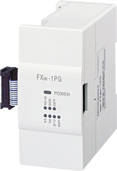 Available on requestFX2N-1PG Mitsubishi MELSEC-F (FX) Series Positioning
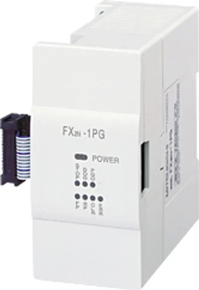 Available on requestFX2N-1PG-E Mitsubishi MELSEC-F (FX) Series Positioning
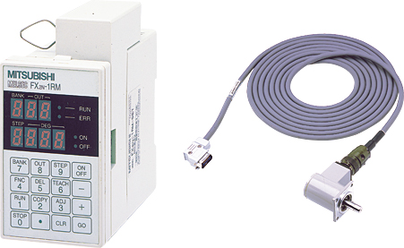 Available on requestFX2N-1RM-E-SET Mitsubishi MELSEC-F (FX) Series Positioning
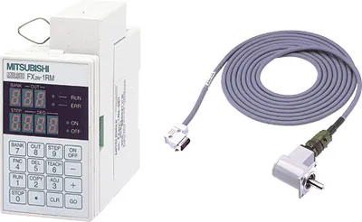 Available on requestFX2N-1RM-SET Mitsubishi MELSEC-F (FX) Series Positioning
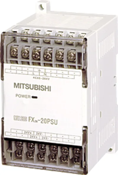 Available on requestFX2N-20PSU Mitsubishi MELSEC-F (FX) Series Option/Training
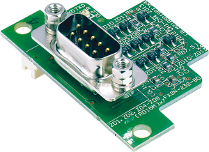 Available on requestFX2N-232-BD Mitsubishi MELSEC-F (FX) Series Data link/Communication
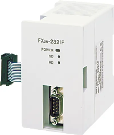 Available on requestFX2N-232IF Mitsubishi MELSEC-F (FX) Series Data link/Communication
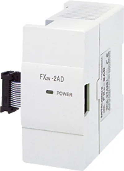 Available on requestFX2N-2AD Mitsubishi MELSEC-F (FX) Series Analog