























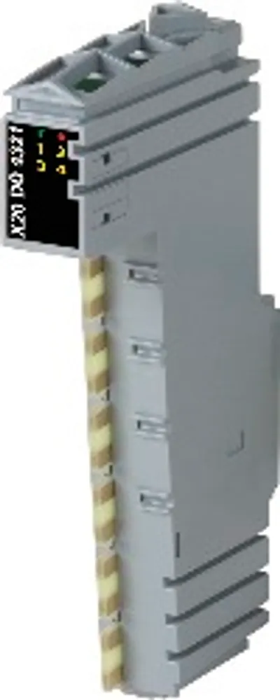
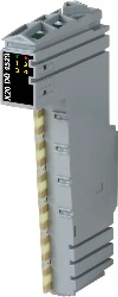
B&R X20DO4332-1
I/O module, 4 digital outputs 24 VDC for 3-wire connections
- MPN
- X20DO4332-1
- Category
- Digital outputs
Price and lead time confirmed within 1 business day
Request a Quote
- 1We check stock, condition and lead time
- 2You get a written quote by email
- 3Approve it and we ship — in-stock parts within 1 business day
- 12-month warranty (new) · 3-month (used/refurbished)
- 30-day returns, no restocking fee on unused parts
- 100% positive eBay feedback
- Ships via



What is the B&R X20DO4332-1?
4 digital outputs with 2 A
Source circuit
3-wire connections
24 VDC and GND for actuator power supply
Integrated output protection
OSP mode
PWM mode
The module is equipped with 4 outputs with 3-wire connections as well as 24 VDC and GND for the actuator power supply. The outputs are designed for a source circuit. The nominal output current is 2 A.
Specifications
Short description
| I/O module | 4 digital outputs 24 VDC for 3-wire connections |
General information
| Diagnostics – Module run/error | Yes, using LED status indicator and software |
| Diagnostics – Outputs | Yes, using LED status indicator and software (output error status) |
| Power consumption – Bus | 0.1 W (Rev. <D0: 0.16 W) |
| Power consumption – Internal I/O | 0.49 W |
| Certifications – CE | Yes |
| Certifications – UKCA | Yes |
| Certifications – CRA (Cyber Resilience Act) | In preparation |
| Certifications – DNV | Temperature: B (0 to 55°C); Humidity: B (up to 100%); Vibration: B (4 g); EMC: B (bridge and open deck) |
| Certifications – CCS | Yes |
| Certifications – LR | ENV1 |
| Certifications – KR | Yes |
| Certifications – ABS | Yes |
| Certifications – BV | EC33B ; Temperature: 5 - 55°C; Vibration: 4 g; EMC: Bridge and open deck |
| B&R ID code | 0xF5F9 |
| Status indicators | I/O function per channel, operating state, module status |
| Additional power dissipation caused by actuators (resistive) [W]Mechanical and electrical configuration" in the X20 system user's manual."> | +1 (Rev. <D0: +1.6) (note: Number of outputs x R DS(on) x Nominal output current 2 . For a calculation example, see section) |
Digital outputs
| Switching delay – 0 → 1 | <300 µs (note: At loads ≤ 1 kΩ) |
| Switching delay – 1 → 0 | <300 µs (note: At loads ≤ 1 kΩ) |
| Switching frequency – Resistive load | Max. 500 Hz (note: At loads ≤ 1 kΩ) |
| Variant | Current-sourcing FET |
| Nominal voltage | 24 VDC |
| Switching voltage | 24 VDC -15% / +20% |
| Nominal output current | 2 A |
| Total nominal current | 8 A |
| Connection type | 3-wire connections |
| Output circuit | Source |
| Output protection | Thermal shutdown in the event of overcurrent or short circuit (see value "Short-circuit peak current"); Internal freewheeling diode for switching inductive loads |
| Actuator power supply | 0.5 A in total for output-independent actuator power supply |
| Diagnostic status | Output monitoring with 10 ms delay |
| Leakage current when the output is switched off | 5 µA |
| R DS(on) | 60 mΩ (Rev. <D0: 100 mΩ) |
| Peak short-circuit current | <4 A |
| Switch-on in the event of overload shutdown or short-circuit shutdown | Approx. 10 ms (depends on the module temperature) |
| Braking voltage when switching off inductive loads | 0.6 V (note: Due to the freewheeling diode integrated in the module.) |
| Insulation voltage between channel and bus | 500 V eff |
| Additional functions | Outputs can be connected in parallel to increase the output current. (note: A parallel connection is not possible in PWM mode.) |
PWM output
| Quantity | 4 |
| Nominal voltage | 24 VDC |
| Nominal current | 2 A |
| PWM frequency | 15.25 to 1000 Hz |
| Output protection | Thermal shutdown in the event of overcurrent or short circuit (see value "Short-circuit peak current"); Internal freewheeling diode for switching inductive loads |
| Variant | Current-sourcing FET |
| Configurable dither | 0 to 250 Hz, 1 to 25% of the period duration |
| Period duration resolution | 1000 to 65535 µs in 1 µs steps |
| Insulation voltage between channel and bus | 500 V eff |
Actuator power supply
| Power consumption – Actuator power supply | Max. 12 W (note: The power consumption of the sensors connected to the module is not permitted to exceed 12 W.) |
| Voltage | Module power supply minus voltage drop for short-circuit protection |
| Voltage drop for short-circuit protection at 500 mA | Max. 2 V |
| Short-circuit proof | Yes |
Electrical properties
| Electrical isolation | Channel isolated from bus; Channel not isolated from channel and I/O power supply |
Operating conditions
| Mounting orientation – Horizontal | Yes |
| Mounting orientation – Vertical | Yes |
| Installation elevation above sea level – 0 to 2000 m | No limitation |
| Installation elevation above sea level – >2000 m | Reduction of ambient temperature by 0.5°C per 100 m |
| Degree of protection per EN 60529 | IP20 |
Ambient conditions
| Temperature – Horizontal mounting orientation | -25 to 60°C |
| Temperature – Vertical mounting orientation | -25 to 50°C |
| Temperature – Derating | See section "Derating". |
| Temperature – Storage | -40 to 85°C |
| Temperature – Transport | -40 to 85°C |
| Relative humidity – Operation | 5 to 95%, non-condensing |
| Relative humidity – Storage | 5 to 95%, non-condensing |
| Relative humidity – Transport | 5 to 95%, non-condensing |
Mechanical properties
| Note | Order 1x terminal block X20TB12 separately.; Order 1x bus module X20BM11 separately. |
| Pitch | 12.5 +0.2 mm |
No matching specifications
Accessories
Required accessories (order separately)
| X20BM15 | Bus modules — The bus module is the base for all X20 24 VDC I/O modules; The internal I/O supply is interconnected; Manual node number assignment; Indepe… |
| X20BM11 | Bus modules — Bus module for 24 VDC I/O modules; The internal I/O power supply is connected through. The bus module is the base for all 24 VDC I/O module… |
| X20TB12 | Terminal blocks — Tool-free wiring with push-in technology; Simple wire release using lever; Ability to label each terminal; Plain text labeling also possibl… |
Downloads & documentation
Official documents from B&R, downloaded directly from the manufacturer.
Data sheets & manuals
CAD & dimension drawings
Certificates (9)
- 64331_A1 BV Certificate of Compliance X20
- CCS Type Approval Certificate - X20
- EU Data Act - X20 IO - Connected Product Information Notice
- EU Declaration ATEX X20
- EU Declaration of conformity PLC X20
- KR Type Approval Certificate MIL39390-AC003 (X20 System)
- Lloyds Register (X20 only)
- TAA00000BJ DNV Type Approval Certificate X20
- UK Declaration PLC X20
X20DO4332-1: frequently asked questions
When can X20DO4332-1 be shipped?
X20DO4332-1 is sourced on request — request a quote and we'll confirm the exact availability and shipping timeline for this specific unit.
Can I pick up X20DO4332-1 in person?
Local pickup from our Groningen, Netherlands warehouse may be possible — contact us before ordering to check availability and arrange a collection time.
Is express delivery available?
Yes — mention it when you request a quote for X20DO4332-1 and we'll include express shipping options in our reply.
My factory is down and I need this urgently — can you help?
For a critical breakdown, contact us directly at +31 (0)50-7110348 or sales@partnerplc.com — we can look into same-day courier or dedicated taxi/hotshot delivery for X20DO4332-1, subject to availability and destination.
More B&R parts
B&R X20DO4332-1Price and lead time confirmed within 1 business day
Request a Quote