B&R
8TB4204.202L-104-pin push-in screw terminal block, two-row, pitch: 10.16 mm, label 2: PE L3 L2 L1, coding L: 1010


We source discontinued Siemens parts on the surplus market, tested and with warranty.
Request a quote
We source discontinued B&R parts on the surplus market, tested and with warranty.
Request a quote
We source discontinued ABB parts on the surplus market, tested and with warranty.
Request a quote
We source discontinued Schneider Electric parts on the surplus market, tested and with warranty.
Request a quote.svg&w=240)
We source discontinued Allen-Bradley parts on the surplus market, tested and with warranty.
Request a quote
We source discontinued Mitsubishi Electric parts on the surplus market, tested and with warranty.
Request a quote
We source discontinued Beckhoff parts on the surplus market, tested and with warranty.
Request a quote
We source discontinued Lenze parts on the surplus market, tested and with warranty.
Request a quote
We source discontinued Bosch Rexroth parts on the surplus market, tested and with warranty.
Request a quote
We source discontinued Danfoss parts on the surplus market, tested and with warranty.
Request a quote
We source discontinued SEW-Eurodrive parts on the surplus market, tested and with warranty.
Request a quote
We source discontinued KUKA parts on the surplus market, tested and with warranty.
Request a quote
We source discontinued Omron parts on the surplus market, tested and with warranty.
Request a quote
We source discontinued Festo parts on the surplus market, tested and with warranty.
Request a quote
We source discontinued WAGO parts on the surplus market, tested and with warranty.
Request a quote
We source discontinued Pilz parts on the surplus market, tested and with warranty.

We source discontinued SICK parts on the surplus market, tested and with warranty.
Request a quote
We source discontinued Pepperl+Fuchs parts on the surplus market, tested and with warranty.
Request a quote
We source discontinued Balluff parts on the surplus market, tested and with warranty.
Request a quote
We source discontinued ifm parts on the surplus market, tested and with warranty.
Request a quoteWe source discontinued Banner parts on the surplus market, tested and with warranty.
Request a quote
We source discontinued Keyence parts on the surplus market, tested and with warranty.
Request a quote
We source discontinued Honeywell parts on the surplus market, tested and with warranty.
Request a quote
We source discontinued Infineon parts on the surplus market, tested and with warranty.
Request a quoteModular mechanical design using plug-in modules



Modular mechanical design using plug-in modules
Integrated line filter
Integrated braking resistor
Integrated electronic restart inhibit
Partially-coated circuit boards - more robust in regard to environmental influences (8Vxxxx.001-2)
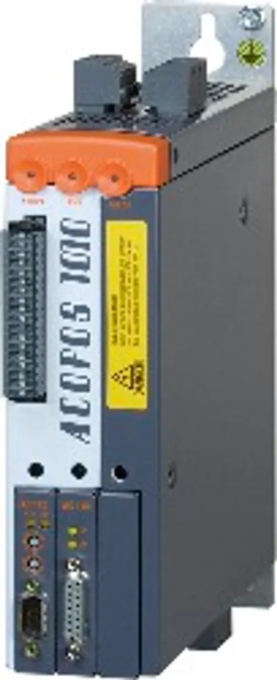
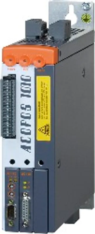
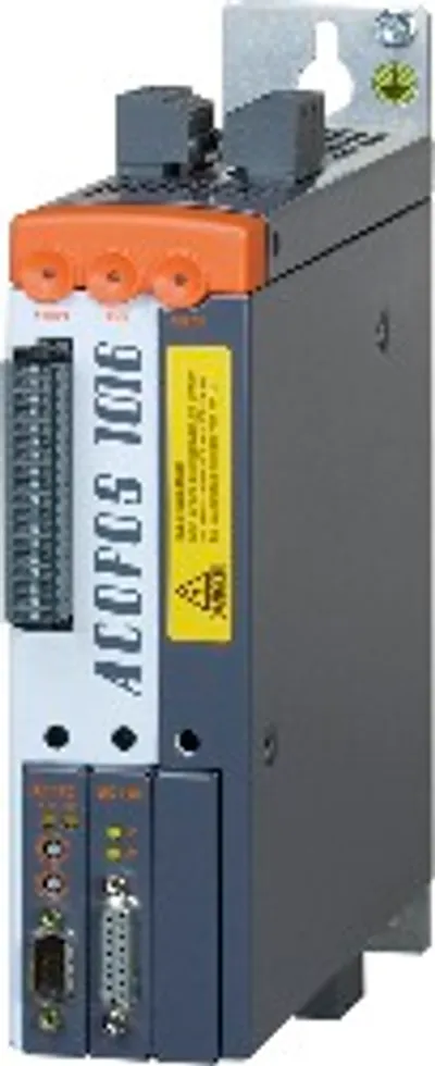
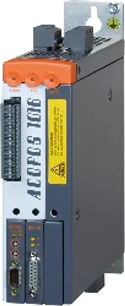
ACOPOS servo drive, 3x 400-480 V, 1.0 A, 0.45 kW, coated, integrated line filter, braking resistor and electronic safe restart interlock
| Certifications – CE | Yes |
| Certifications – UKCA | Yes |
| Certifications – CRA (Cyber Resilience Act) | Non-compliant |
| Certifications – Functional safety | Yes |
| Certifications – UL | cULus E225616; Power conversion equipment |
| Certifications – KC | Yes |
| Note | Variant with partially coated printed circuit boards |
| B&R ID code | 0xA6D4 |
| Slots for plug-in modules | 3 |
| Permissible network configurations | TT, TNDelta/Wye with grounded wye neutral" in the USA."> (note: TT and TN power systems are commonly referred to as) |
| Mains input voltage | 3x 400 VAC to 480 VAC ±10%; 3x 230 VAC ±10% (note: If the module is operated with a mains input voltage of 3x 230 VAC, then automatic nominal voltage detection does not work for the DC bus. Parameter UDC_NOMINAL must be set to 325 [V] by the user in this case.) |
| Frequency | 50 / 60 Hz ±4% |
| Installed load | Max. 1.35 kVA |
| Inrush current | 2 A (at 400 VAC) |
| Switch-on interval | >10 s |
| Integrated line filter per EN 61800-3, category C3 | Yes (note: Limit values from EN 61800-3 C3 (second environment).) |
| Power dissipation at device nominal power without braking resistor | 80 W |
| DC bus capacitance | 165 µF |
| Input voltage | 24 VDC +25% / -20% (note: The permissible input voltage range is reduced when using motor holding brakes. The input voltage range must be selected so that the permissible supply voltage of the motor holding brake is maintained.) |
| Input capacitance | 5600 µF |
| Current consumption | Max. 1.47 A + Current for motor holding brake (note: Current consumption depends on the respective configuration of the ACOPOS servo drive. The inrush current is significantly higher than the value for current consumption and can be estimated according to the input capacitance.) |
| Reduction of continuous current depending on ambient temperature – Switching frequency 5 kHz | No reduction |
| Reduction of continuous current depending on ambient temperature – Switching frequency 10 kHz | No reduction (note: Value for the nominal switching frequency.) |
| Reduction of continuous current depending on ambient temperature – Switching frequency 20 kHz | No reduction |
| Reduction of continuous current depending on ambient temperature – Switching frequency 5 kHz | No reduction |
| Reduction of continuous current depending on ambient temperature – Switching frequency 10 kHz | No reduction (note: Value for the nominal switching frequency.) |
| Reduction of continuous current depending on ambient temperature – Switching frequency 20 kHz | 0.13 A eff per °C (starting at 45°C) |
| Reduction of continuous current depending on installation elevation – Starting at 500 m above sea level | 0.1 A eff per 1000 m |
| Protective measures – Overload protection | Yes |
| Protective measures – Short-circuit and ground fault protection | Yes |
| Terminal connection cross section – With wire end sleeve | 0.25 to 4 mm² |
| Terminal connection cross section – UL/C-UL-US | 30 to 10 AWG |
| Terminal connection cross section – CSA | 28 to 10 AWG |
| Quantity | 1 |
| Continuous current | 1 A eff (note: Valid under the following conditions: mains input voltage 400 VAC, nominal switching frequency, 40°C ambient temperature, installation elevation <500 m above sea level.) |
| Peak current | 2.8 A eff |
| Nominal switching frequency | 10 kHz |
| Possible switching frequencies | 5 / 10 / 20 kHz |
| Insulation stress of the connected motor per IEC TS 60034-25:2004 | Limit value curve A |
| Max. motor line length | 15 m |
| Max. output frequency | 598 HzPower unit: Limit speed exceeded")."> |
| Response threshold for open-circuit monitoring | Approx. 245 mA |
| Max. output current | 1.3 A |
| Max. number of switching cycles | Unlimited since implemented electronically |
| Peak power output | 2 kW |
| Continuous power | 130 W |
| Electrical isolation – Input - ACOPOS | Yes |
| Electrical isolation – Input - Input | No |
| Input voltage – Nominal | 24 VDC |
| Input voltage – Maximum | 30 VDC |
| Switching threshold – Low | <5 V |
| Switching threshold – High | >15 V |
| Quantity | 3 |
| Circuit | Sink |
| Input current at nominal voltage | Approx. 4 mA |
| Switching delay | Max. 2.0 ms |
| Modulation compared to ground potential | Max. ±38 V |
| Electrical isolation – Input - ACOPOS | Yes |
| Input voltage – Nominal | 24 VDC |
| Input voltage – Maximum | 30 VDC |
| Switching threshold – Low | <5 V |
| Switching threshold – High | >15 V |
| Switching delay – Enable 0 → 1, ready for PWM | Max. 100 µs |
| Switching delay – Enable 1 → 0, PWM off | Max. 2.0 ms |
| Quantity | 1 |
| Circuit | Sink |
| Input current at nominal voltage | Approx. 30 mA |
| Modulation compared to ground potential | Max. ±38 V |
| OSSD signal connections | Not permitted (note: OSSD (output signal switching device) signals are used to monitor signal lines for short circuits and cross faults.) |
| Electrical isolation – Input - ACOPOS | Yes |
| Electrical isolation – Input - Input | No |
| Input voltage – Nominal | 24 VDC |
| Input voltage – Maximum | 30 VDC |
| Switching threshold – Low | <5 V |
| Switching threshold – High | >15 V |
| Switching delay – Rising edge | 52 µs ±0.5 µs (digitally filtered) |
| Switching delay – Falling edge | 53 µs ±0.5 µs (digitally filtered) |
| Quantity | 2 |
| Circuit | Sink |
| Input current at nominal voltage | Approx. 10 mA |
| Modulation compared to ground potential | Max. ±38 V |
| Energy efficiency (IE classification) – Power dissipation relative to continuous apparent power | IE2 (10,25) 6.9% ; IE2 (50,25) 6.9% ; IE2 (10,50) 6.9% ; IE2 (50,50) 6.9% ; IE2 (90,50) 7% ; IE2 (10,100) 7.1% ; IE2 (50,100) 7.2% ; IE2 (90,100) 7.3% |
| Energy efficiency (IE classification) – Nominal losses in standby mode | 12.5 W |
| Discharge capacitance | 550 nF |
| Permissible mounting orientations – Hanging vertically | Yes |
| Permissible mounting orientations – Horizontal, face up | Yes |
| Permissible mounting orientations – Standing horizontally | No |
| Installation elevation above sea level – Nominal | 0 to 500 m |
| Installation elevation above sea level – Maximum | 2000 m (note: Continuous operation of ACOPOS servo drives at an installation elevation from 500 m to 2000 m above sea level is possible (taking the specified continuous current reductions into account).) |
| Pollution degree per EN 61800-5-1 | 2 (non-conductive pollution) |
| Overvoltage category per EN 61800-5-1 | II |
| Degree of protection per EN 60529 | IP20 |
| Temperature – Nominal | 5 to 40°C |
| Temperature – Maximum | 55°C (note: Continuous operation of the ACOPOS servo drive at an ambient temperature of 40°C to max. 55°C is possible taking the specified reduction of continuous torque into account, but this results in premature aging of components.) |
| Temperature – Storage | -25 to 55°C |
| Temperature – Transport | -25 to 70°C |
| Relative humidity – Operation | 5 to 85% |
| Relative humidity – Storage | 5 to 95% |
| Relative humidity – Transport | Max. 95% at 40°C |
| Dimensions – Width | 58.5 mm |
| Dimensions – Height | 257 mm |
| Dimensions – Depth | 220 mm |
| Weight | 2.5 kg |
| 8X0040.00-1 | Shield component sets — ACOPOS shield component set for 8V1010.xxx-x and 8V1016.xxx-x |
| 8X0001.00-1 | Terminal block sets — ACOPOS accessories, connector set for 8V1010.00 to 8V1090.00 (3-phase) |
| 8AC131.60-1 | Plug-in modules — Mixed module for installation in ACOPOS servo drives; 2 analog inputs with 12-bit resolution and a maximum of 2 digital inputs/outputs; Ind… |
| 8AC130.60-1 | Plug-in modules — Digital mixed module for installation in ACOPOS servo drives; Maximum of 8 digital inputs or 10 digital outputs; I/O configurable in pairs… |
| 8AC126.60-1 | Plug-in modules — EnDat 2.2 encoder interface for installation in ACOPOS servo drives; Encoder monitoring; Embedded parameter chip when used with B&R motors;… |
| 8AC125.61-2 | Plug-in modules — BiSS encoder interface (Mode C) for installation in ACOPOS servo drives; 6.25 Mbit/s, 12 V encoder supply; Encoder monitoring ACOPOS plug-i… |
| 8AC125.60-2 | Plug-in modules — BiSS encoder interface (Mode C) for installation in ACOPOS servo drives; Encoder supply 5 V; Encoder monitoring ACOPOS plug-in module, BiSS… |
| 8AC125.60-1 | Plug-in modules — BiSS encoder interface (Mode C) for installation in ACOPOS servo drives; Encoder supply 5 V; Encoder monitoring ACOPOS plug-in module, BiSS… |
| 8AC123.60-1 | Plug-in modules — Incremental encoder and SSI absolute encoder interface for installation in ACOPOS servo drives; Monitors encoder input signals; Encoder sup… |
| 8AC122.60-3 | Plug-in modules — Resolver interface for installation in ACOPOS servo drives; Monitors encoder input signals; Resolver type BRX ACOPOS plug-in module, resolv… |
| 8AC121.60-1 | Plug-in modules — HIPERFACE interface for installation in ACOPOS servo drives; Encoder monitoring ACOPOS plug-in module, HIPERFACE interface |
| 8AC120.60-1 | Plug-in modules — EnDat 2.1 encoder interface for installation in ACOPOS servo drives; Encoder monitoring; Also suitable for evaluating simple incremental en… |
| 8AC114.60-2 | Plug-in modules — POWERLINK interface for installation in ACOPOS servo drives; Integrated 2-port hub for easy wiring; For communication and configuration of… |
| 8AC110.60-3 | Plug-in modules — ACOPOS plug-in module, CAN interface |
Official documents from B&R, downloaded directly from the manufacturer.
8V1010.001-2 is sourced on request — request a quote and we'll confirm the exact availability and shipping timeline for this specific unit.
Local pickup from our Groningen, Netherlands warehouse may be possible — contact us before ordering to check availability and arrange a collection time.
Yes — mention it when you request a quote for 8V1010.001-2 and we'll include express shipping options in our reply.
For a critical breakdown, contact us directly at +31 (0)50-7110348 or sales@partnerplc.com — we can look into same-day courier or dedicated taxi/hotshot delivery for 8V1010.001-2, subject to availability and destination.
4-pin push-in screw terminal block, two-row, pitch: 10.16 mm, label 2: PE L3 L2 L1, coding L: 1010
4-pin screw clamp terminal block, one-row, pitch: 3.81 mm, label 1: Numbered consecutively
4-pin push-in terminal block, one-row, pitch: 3.81 mm, label 1: Numbered consecutively