























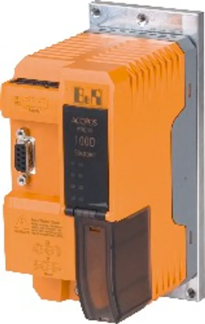
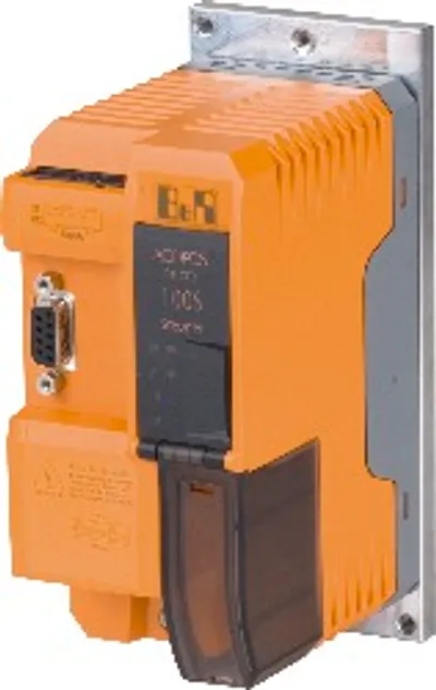
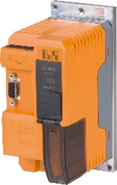
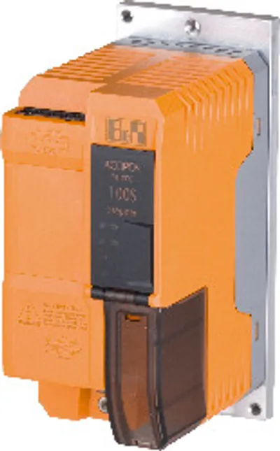
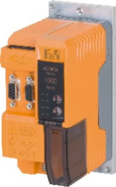
B&R 80SD100XD.W0XX-01
Stepper motor module, connection for two stepper motors…
- MPN
- 80SD100XD.W0XX-01
- Category
- Stepper motor modules
Price and lead time confirmed within 1 business day
Request a Quote
- 12-month warranty (new) · 3-month (used/refurbished)
- 30-day returns, no restocking fee on unused parts
- Ships via



- 100% positive eBay feedback
What is the B&R 80SD100XD.W0XX-01?
Control for 2 stepper motors (2-phase bipolar, full bridge)
256 microsteps per step
2 trigger inputs
Motor holding brake connection
Enable input
Automatic motor identification
Holding, boost and continuous current can be defined independent of one another
Heat sink
ACOPOSmicro stepper motor module, heat sink, X2X Link interface, 24-64 VDC ±25% power supply, 2 motor connections, 10 A continuous current, 2 digital inputs 24 VDC, sink, can be used as trigger inputs, 1 digital output 24 VDC, 1 A, order terminal blocks separately!
Specifications
Short description
| Stepper motor module | Connection for two stepper motors without encoder, 2-phase bipolar |
General information
| Diagnostics – Module run/error | Yes, using LED status indicator and software |
| Diagnostics – Module temperature / Cooling unit temperature | Yes, using software |
| Diagnostics – Motor status | Yes, using LED status indicator and software |
| Diagnostics – X2X Link | Yes, using LED status indicator |
| Electrical isolation – CPU - 24 VDC power supply | No |
| Electrical isolation – CPU - Power supply | Yes |
| Electrical isolation – CPU - Motor connection | Yes |
| Electrical isolation – CPU - Digital inputs | Yes |
| Electrical isolation – CPU - Enable inputs | Yes |
| Electrical isolation – CPU - Motor holding brake | No |
| Electrical isolation – CPU - X2X Link | Yes |
| Certifications – CE | Yes |
| Certifications – UKCA | Yes |
| Certifications – CRA (Cyber Resilience Act) | In preparation |
| Certifications – Functional safety | Yes |
| Certifications – UL | cULus E225616; Power conversion equipment |
| Certifications – KC | Yes |
| B&R ID code | 0xC641 |
| Status indicators | X2X Link, operating state, module status, motor information |
24 VDC power supply
| Power consumption – CPU | Max. 6 W (note: Including the enable input.) |
| Power consumption – X2X Link power supply | Generated internally from the CPU power supply |
| Input voltage | 24 VDC ±25% |
| Voltage monitoring | Yes |
| Reverse polarity protection | Yes |
Power supply
| Power consumption – Idle (no motor powered) | Max. 0.5 W |
| Power consumption – Full load | See diagram "Dimensioning - Power dissipation from the power unit for each powered axis" |
| Input voltage | 24 to 64 VDC ±25% |
| Inrush current | Max. 10 A |
| Inrush current limiting | Yes, PTC (min. 9 Ω), is bypassed during operation by means of relay contact. |
| Undervoltage cutoff | <18 VDC |
| Overvoltage cutoff | >95 VDC |
| Voltage measurement | Yes |
| Line protection | Must occur externally |
| Reverse polarity protection | Yes |
Motor connection
| Quantity | 2 |
| Nominal current | 10 A Peak |
| Max. current/motor | 15 A Peak (2 s) |
| Max. current/module | 30 A Peak |
| Nominal switching frequency | 38.5 kHz |
| Max. motor line length | 25 m |
| Step resolution | 256 microsteps per full step |
| DC bus capacitance | 940 µF |
Motor holding brake connection
| Switching frequency – Resistive load | 100 Hz |
| Switching frequency – Inductive load | See section "Switching inductive loads" |
| Protective measures – Overload and short-circuit protection | Yes |
| Protective measures – Open-circuit monitoring | No |
| Protective measures – Undervoltage monitoring | Yes |
| Quantity | 1 |
| Nominal voltage | 24 VDC |
| Input voltage | 24 VDC ±25% |
| Continuous current per connection | 1 A |
| Max. internal resistance | 0.3 Ω |
| Max. overcurrent limiting | 8 A |
| Response threshold for undervoltage monitoring | ≤11 VDC |
| Reference potential | GND for module power supply (X2 terminal, pin 10) |
Interfaces
| X2X – Variant | 4-pin male connector |
| X2X – Min. X2X Link cycle time | 250 μs |
Enable inputs
| Switching threshold – Low | <5 VDC |
| Switching threshold – High | >15 VDC |
| Switching delay at nominal input voltage – Maximum | 450 ms (Rev. < G0: 452 ms) |
| Switching delay at nominal input voltage – Maximum | 500 ms |
| Quantity | 1 |
| Nominal voltage | 24 VDC |
| Input voltage | 24 VDC ±25% |
| Input current at nominal voltage | Typ. 60 mA |
| Input circuit | Sink |
| Insulation voltage between input and bus | 500 V eff |
| Input capacitance | 10 nF (Rev. < G0: 100 µF) |
Digital inputs / Trigger inputs
| Input voltage – Nominal | 24 VDC |
| Input voltage – Maximum | 30 VDC |
| Switching threshold – Low | <5 VDC |
| Switching threshold – High | >15 VDC |
| Switching delay – Rising edge | [Instant recording] Typ. 3 µs |
| Switching delay – Falling edge | [Instant recording] Typ. 4 µs |
| Electrical isolation – Input - ACOPOS | Yes, 500 V eff |
| Electrical isolation – Input - Input | Yes, 500 V eff |
| Quantity | 2 |
| Additional functions | Can be used as trigger input |
| Input circuit | Sink |
| Input current at nominal voltage | Approx. 7.5 mA |
| Input resistance | Approx. 3.2 kΩ |
| Modulation compared to ground potential | Max. ±38 V |
Operating conditions
| Mounting orientation – Horizontal | No |
| Mounting orientation – Vertical | Yes |
| Pollution degree per EN 61800-5-1 | 2 (non-conductive pollution) |
| Degree of protection per EN 60529 | IP20 |
Ambient conditions
| Temperature – Operation | 0 to 45 °C |
| Temperature – Storage | -25 to 55 °C |
| Temperature – Transport | -25 to 55 °C |
| Relative humidity – Operation | 5 to 85 %, non-condensing |
| Relative humidity – Storage | 5 to 95%, non-condensing |
| Relative humidity – Transport | 5 to 95%, non-condensing |
Mechanical properties
| Dimensions – Width | 65 mm (note: Without heat sink) |
| Dimensions – Height | 134 mm (note: Without heat sink) |
| Dimensions – Depth | 95 mm (note: Without heat sink) |
| Note | Order terminal blocks and cables separately! |
| Mounting/Cooling | Heat sink for wall mounting |
| Weight | 930 g |
Accessories
Required accessories (order separately)
| 80XSD100XD.C0-01B | Terminal block sets — Cage clamp terminal block set for ACOPOSmicro modules 80SD100XD.xxxx-01: 1x 0TB1110.8110, 1x 0TB2105.4121-01, 1x 0TB2105.4122-01, 1x 0TB210… |
| 80XSD100XD.C0-01A | Terminal block sets — Screw clamp terminal block set for ACOPOSmicro modules 80SD100XD.xxxx-01: 1x 0TB1110.8010, 1x 0TB2105.4021, 1x 0TB2105.4022, 1x 0TB2105.9021 |
Optional accessories (4)
| 80XSC0000.00-10 | Hose clamps — Accessory for ACOPOSmicro: 10x hose clamp, B 9 mm, D 8-12 mm |
| 80XSC0000.00-01 | Hose clamps — Accessory for ACOPOSmicro: 1x hose clamp, B 9 mm, D 8-12 mm |
| 0TB1310.8110 | Terminal blocks — Accessory terminal block, 3x 10-pin, cage clamp terminal block 1.5 mm², protected against vibration by the screw flange, with labeling |
| 0TB1310.3100 | Terminal blocks — Accessory terminal block, 3x 10-pin, cage clamp terminal block, 1.5 mm², protected against vibration by the screw flange |
Downloads & documentation
Official documents from B&R, downloaded directly from the manufacturer.
Data sheets & manuals
CAD & dimension drawings
80SD100XD.W0XX-01: frequently asked questions
When can 80SD100XD.W0XX-01 be shipped?
80SD100XD.W0XX-01 is sourced on request — request a quote and we'll confirm the exact availability and shipping timeline for this specific unit.
Can I pick up 80SD100XD.W0XX-01 in person?
Local pickup from our Groningen, Netherlands warehouse may be possible — contact us before ordering to check availability and arrange a collection time.
Is express delivery available?
Yes — mention it when you request a quote for 80SD100XD.W0XX-01 and we'll include express shipping options in our reply.
My factory is down and I need this urgently — can you help?
For a critical breakdown, contact us directly at +31 (0)50-7110348 or sales@partnerplc.com — we can look into same-day courier or dedicated taxi/hotshot delivery for 80SD100XD.W0XX-01, subject to availability and destination.
More B&R parts
B&R 80SD100XD.W0XX-01Price and lead time confirmed within 1 business day
Request a Quote