























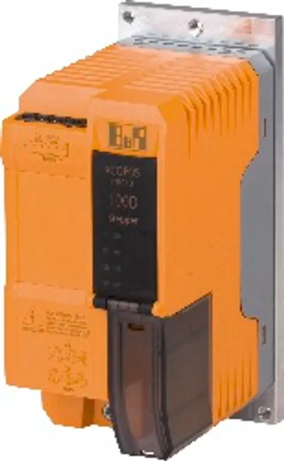
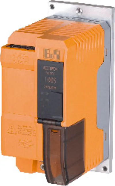
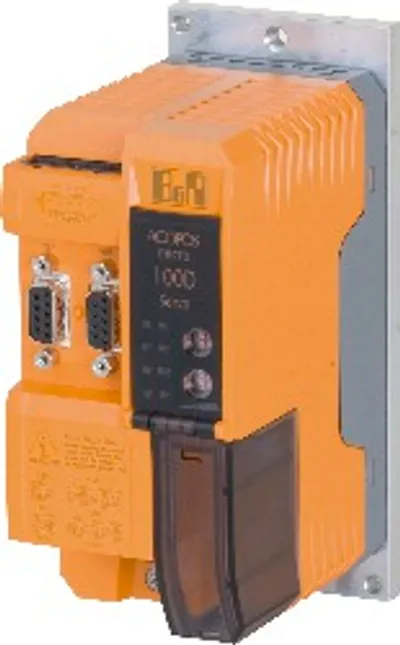
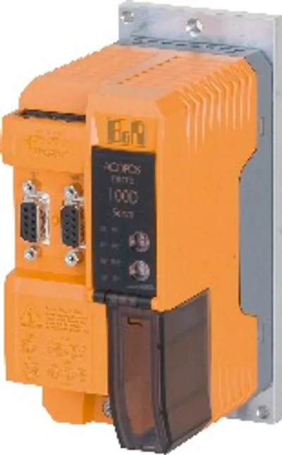
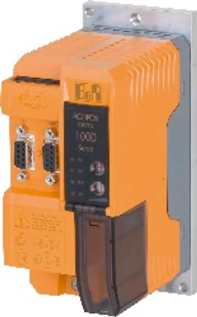
B&R 80SD100XS.C04X-13
Stepper motor module, connection for 1 stepper motor with…
- MPN
- 80SD100XS.C04X-13
- Category
- Stepper motor modules
Price and lead time confirmed within 1 business day
Request a Quote
- 12-month warranty (new) · 3-month (used/refurbished)
- 30-day returns, no restocking fee on unused parts
- Ships via



- 100% positive eBay feedback
What is the B&R 80SD100XS.C04X-13?
Control for 1 stepper motor (2-phase bipolar, full bridge)
256 microsteps per step
1 incremental encoder input
2 trigger inputs
Motor holding brake connection
Enable input
Automatic motor identification
Holding, boost and continuous current can be defined independent of one another
4 digital inputs, 24 VDC, sink
2 digital outputs, 24 VDC, 0.5 A
ACOPOSmicro stepper motor module, X2X Link interface, 1x 24 V incremental encoder, 24-64 VDC ±25% power supply, 1 motor connection, 10 A continuous current, 2 digital inputs 24 VDC, sink, can be used as trigger inputs, 1 digital output 24 VDC, 1 A, 4 digital inputs 24 VDC, sink, configurable as incremental encoder, 2 digital outputs 24 VDC, 0.5 A order terminal blocks separately!
Specifications
Short description
| Stepper motor module | Connection for 1 stepper motor with ABR incremental encoder, 2-phase bipolar |
General information
| Diagnostics – Module run/error | Yes, using LED status indicator and software |
| Diagnostics – Module temperature / Cooling unit temperature | Yes, using software |
| Diagnostics – Motor status | Yes, using LED status indicator and software |
| Diagnostics – X2X Link | Yes, using LED status indicator |
| Electrical isolation – CPU - 24 VDC power supply | No |
| Electrical isolation – CPU - Power supply | Yes |
| Electrical isolation – CPU - Motor connection | Yes |
| Electrical isolation – CPU - Digital inputs | Yes |
| Electrical isolation – CPU - Enable inputs | Yes |
| Electrical isolation – CPU - Optional inputs/outputs | No |
| Electrical isolation – CPU - Encoder | No |
| Electrical isolation – CPU - Motor holding brake | No |
| Electrical isolation – CPU - X2X Link | Yes |
| Certifications – CE | Yes |
| Certifications – UKCA | Yes |
| Certifications – CRA (Cyber Resilience Act) | In preparation |
| Certifications – Functional safety | Yes |
| Certifications – UL | cULus E225616; Power conversion equipment |
| Certifications – KC | Yes |
| B&R ID code | 0xA782 |
| Status indicators | X2X Link, operating state, module status, motor information |
24 VDC power supply
| Power consumption – CPU | Max. 7 W (note: Including the enable input.) |
| Power consumption – X2X Link power supply | Generated internally from the CPU power supply |
| Input voltage | 24 VDC ±25% |
| Voltage monitoring | Yes |
| Reverse polarity protection | Yes |
Power supply
| Power consumption – Idle (no motor powered) | Max. 0.5 W |
| Power consumption – Full load | See diagram "Dimensioning - Power dissipation from the power unit for each powered axis" |
| Input voltage | 24 to 64 VDC ±25% |
| Inrush current | Max. 10 A |
| Inrush current limiting | Yes, PTC (min. 9 Ω), is bypassed during operation by means of relay contact. |
| Undervoltage cutoff | <18 VDC |
| Overvoltage cutoff | >95 VDC |
| Voltage measurement | Yes |
| Line protection | Must occur externally |
| Reverse polarity protection | Yes |
Motor connection
| Quantity | 1 |
| Nominal current | 10 A Peak |
| Max. current/motor | 15 A Peak (2 s) |
| Max. current/module | 15 A Peak |
| Nominal switching frequency | 38.5 kHz |
| Max. motor line length | 25 m |
| Step resolution | 256 microsteps per full step |
| DC bus capacitance | 940 µF |
Motor holding brake connection
| Switching frequency – Resistive load | 100 Hz |
| Switching frequency – Inductive load | See section "Switching inductive loads" |
| Protective measures – Overload and short-circuit protection | Yes |
| Protective measures – Open-circuit monitoring | No |
| Protective measures – Undervoltage monitoring | Yes |
| Quantity | 1 |
| Nominal voltage | 24 VDC |
| Input voltage | 24 VDC ±25% |
| Continuous current per connection | 1 A |
| Max. internal resistance | 0.3 Ω |
| Max. overcurrent limiting | 8 A |
| Response threshold for undervoltage monitoring | ≤11 VDC |
| Reference potential | GND for module power supply (X2 terminal, pin 10) |
Interfaces
| X2X – Variant | 4-pin male connector |
| X2X – Min. X2X Link cycle time | 250 μs |
Encoder inputs
| Encoder power supply – Overload-proof | Yes |
| Encoder power supply – Short-circuit proof | Yes |
| Encoder power supply – Output voltage | 24 V (note: Depends on the supply voltage of the CPU component.) |
| Encoder power supply – Load capacity | 40 mAIncremental encoder - Input circuit diagram" in chapter "X6 - Encoder inputs""> (note: See section) |
| Inputs A, B, R – Low | <5 V (against COM) |
| Inputs A, B, R – High | >15 V (against COM) |
| Temperature measurement – Type | KTY |
| Temperature measurement – Values | 0 to 110 °C |
| Temperature measurement – Tolerance | 5% |
| Quantity | 1 |
| Type | ABR single-ended signals 24 V |
| Max. encoder cable length | 25 m |
Incremental encoder operation
| Signal form | Square wave pulse |
| Evaluation | 4x |
| Counter size | 16-bit |
| Input frequency | Max. 50 kHz |
| Counter frequency | 200 kHz |
| Input current at nominal voltage | Typ. 4 mA |
Enable inputs
| Switching threshold – Low | <5 VDC |
| Switching threshold – High | >15 VDC |
| Switching delay at nominal input voltage – Maximum | 500 ms (Rev. < K0: 867 ms) |
| Switching delay at nominal input voltage – Maximum | 500 ms |
| Quantity | 1 |
| Nominal voltage | 24 VDC |
| Input voltage | 24 VDC ±25% |
| Input current at nominal voltage | Typ. 60 mA |
| Input circuit | Sink |
| Insulation voltage between input and bus | 500 V eff |
| Input capacitance | 10 nF (Rev. < K0: 100 µF) |
Digital inputs / Trigger inputs
| Input voltage – Nominal | 24 VDC |
| Input voltage – Maximum | 30 VDC |
| Switching threshold – Low | <5 VDC |
| Switching threshold – High | >15 VDC |
| Switching delay – Rising edge | [Instant recording] Typ. 3 µs |
| Switching delay – Falling edge | [Instant recording] Typ. 4 µs |
| Electrical isolation – Input - ACOPOS | Yes, 500 V eff |
| Electrical isolation – Input - Input | Yes, 500 V eff |
| Quantity | 2 |
| Additional functions | 1 input usable as trigger input |
| Input circuit | Sink |
| Input current at nominal voltage | Approx. 7.5 mA |
| Input resistance | Approx. 3.2 kΩ |
| Modulation compared to ground potential | Max. ±38 V |
Digital inputs (option board)
| Input voltage – Nominal | 24 VDC |
| Input voltage – Maximum | 30 VDC |
| Switching threshold – Low | <5 VDC |
| Switching threshold – High | >15 VDC |
| Switching delay – Rising edge | [Instant recording] Typ. 2 µs |
| Switching delay – Falling edge | [Instant recording] Typ. 3 µs |
| Electrical isolation – Input - ACOPOS | No |
| Electrical isolation – Input - Input | No |
| Quantity | 4 |
| Additional functions | Incremental encoder, event counter, period or gate measurement |
| Input circuit | Sink |
| Nominal voltage | 24 VDC |
| Input voltage | 24 VDC ±25% |
| Input current at nominal voltage | Approx. 3.1 mA |
| Input resistance | Approx. 7.8 kΩ |
Incremental encoder (option board)
| Counter size | 16-bit |
| Input frequency | Max. 25 kHz |
| Evaluation | 4x |
Event counter (option board)
| Quantity | 1 |
| Signal form | Square wave pulse |
| Input frequency | Max. 50 kHz |
| Counter size | 16-bit |
| Evaluation | Configurable |
Gate time measurement (option board)
| Quantity | 1 |
| Signal form | Square wave pulse |
| Evaluation | Configurable |
| Pulse length | ≥10 µs |
| Length of pause between pulses | ≥10 µs |
| Counter frequency | Configurable |
| Counter size | 16-bit |
Digital outputs (option board)
| Switching delay – 0 → 1 | Max. 250 µs |
| Switching delay – 1 → 0 | Max. 270 µs |
| Switching frequency – Resistive load | 100 Hz |
| Switching frequency – Inductive load | See section "Switching inductive loads" |
| Quantity | 2 |
| Nominal voltage | 24 VDC |
| Switching voltage | 24 VDC ±25% |
| Connection type | 1-wire connections |
| Output circuit | Source |
| Output protection | Thermal shutdown in the event of overcurrent or short circuit |
| Variant | High-side current-sourcing FET |
| Braking voltage when switching off inductive loads | 47 V |
| Supply voltage | From the 24 VDC power supply |
| Max. internal resistance | 0.3 Ω |
| Continuous current per output | 0.5 A |
| Continuous current of all outputs | 1.0 A (note: The power required by the CPU is increased by the current consumed by the outputs.) |
| Switching on after overload shutdown | Typ. 10 ms (depends on the module temperature) |
Operating conditions
| Mounting orientation – Horizontal | No |
| Mounting orientation – Vertical | Yes |
| Pollution degree per EN 61800-5-1 | 2 (non-conductive pollution) |
| Degree of protection per EN 60529 | IP20 |
Ambient conditions
| Temperature – Operation | 0 to 45 °C |
| Temperature – Storage | -25 to 55 °C |
| Temperature – Transport | -25 to 55 °C |
| Relative humidity – Operation | 5 to 85 %, non-condensing |
| Relative humidity – Storage | 5 to 95%, non-condensing |
| Relative humidity – Transport | 5 to 95%, non-condensing |
Mechanical properties
| Dimensions – Width | 65 mm (note: Without heat spreader) |
| Dimensions – Height | 134 mm (note: Without heat spreader) |
| Dimensions – Depth | 95 mm (note: Without heat spreader) |
| Note | Order terminal blocks and cables separately! |
| Mounting/Cooling | Screw mounting with heat spreader on mounting plate or cold-plate. |
| Weight | 700 g |
| Backplane | Always mount on conductive and earthed backplane. |
Accessories
Required accessories (order separately)
| 80XSD100XS.C0-13B | Terminal block sets — Cage clamp terminal block set for ACOPOSmicro modules 80SD100XS.xxxx-13: 1x 0TB1110.8110, 1x 0TB1106.8110, 1x 0TB2105.4121-01, 1x 0TB2105.9… |
| 80XSD100XS.C0-13A | Terminal block sets — Screw clamp terminal block set for ACOPOSmicro modules 80SD100XS.xxxx-13: 1x 0TB1110.8010, 1x 0TB1106.8010, 1x 0TB2105.4021, 1x 0TB2105.9021 |
Optional accessories (4)
| 80XSC0000.00-10 | Hose clamps — Accessory for ACOPOSmicro: 10x hose clamp, B 9 mm, D 8-12 mm |
| 80XSC0000.00-01 | Hose clamps — Accessory for ACOPOSmicro: 1x hose clamp, B 9 mm, D 8-12 mm |
| 0TB1310.8110 | Terminal blocks — Accessory terminal block, 3x 10-pin, cage clamp terminal block 1.5 mm², protected against vibration by the screw flange, with labeling |
| 0TB1310.3100 | Terminal blocks — Accessory terminal block, 3x 10-pin, cage clamp terminal block, 1.5 mm², protected against vibration by the screw flange |
Downloads & documentation
Official documents from B&R, downloaded directly from the manufacturer.
Data sheets & manuals
CAD & dimension drawings
80SD100XS.C04X-13: frequently asked questions
When can 80SD100XS.C04X-13 be shipped?
80SD100XS.C04X-13 is sourced on request — request a quote and we'll confirm the exact availability and shipping timeline for this specific unit.
Can I pick up 80SD100XS.C04X-13 in person?
Local pickup from our Groningen, Netherlands warehouse may be possible — contact us before ordering to check availability and arrange a collection time.
Is express delivery available?
Yes — mention it when you request a quote for 80SD100XS.C04X-13 and we'll include express shipping options in our reply.
My factory is down and I need this urgently — can you help?
For a critical breakdown, contact us directly at +31 (0)50-7110348 or sales@partnerplc.com — we can look into same-day courier or dedicated taxi/hotshot delivery for 80SD100XS.C04X-13, subject to availability and destination.
More B&R parts
B&R 80SD100XS.C04X-13Price and lead time confirmed within 1 business day
Request a Quote