























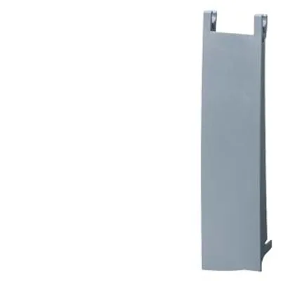
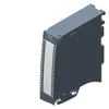
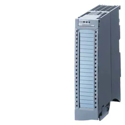
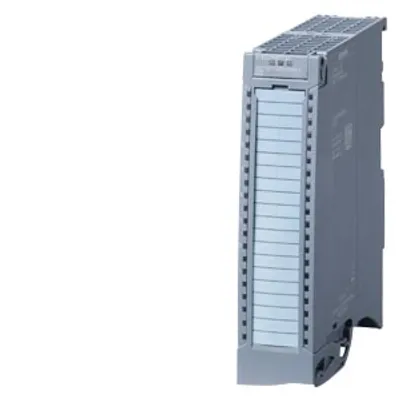
Siemens 6ES7531-7TF00-0AB0
SIMATIC S7-1500, analog input module AI 8xHART HF, accuracy 0.1%, 8 channels in groups of 4
- MPN
- 6ES7531-7TF00-0AB0
- Category
- SM 531 analog input modules
Price and lead time confirmed within 1 business day
Request a Quote
- 12-month warranty (new) · 3-month (used/refurbished)
- 30-day returns, no restocking fee on unused parts
- Ships via



- 100% positive eBay feedback
What is the Siemens 6ES7531-7TF00-0AB0?
SIMATIC S7-1500, analog input module AI 8xHART HF, accuracy 0.1%, 8 channels in groups of 4, common mode voltage: 30 V AC/60 V DC, diagnostics; hardware interrupts calibrate in RUN; delivery including infeed element, shielding bracket and shield terminal
Specifications
General information
| Product type designation | AI 8xHART HF |
| HW functional status | from FS01 |
| Firmware version | V1.0.0 |
| Firmware version — FW update possible | Yes |
| Product function — I&M data | Yes; I&M0 to I&M3 |
| Product function — Isochronous mode | No |
| Product function — Prioritized startup | No |
| Product function — Measuring range scalable | No |
| Product function — Scalable measured values | No |
| Product function — Adjustment of measuring range | No |
| Engineering with — STEP 7 TIA Portal configurable/integrated from version | V17/V18 with HSP 383 |
| Engineering with — STEP 7 configurable/integrated from version | V5.5 SP3 / - |
| Engineering with — PROFIBUS from GSD version/GSD revision | V1.0 / V5.1 |
| Engineering with — PROFINET from GSD version/GSD revision | V2.42 / - |
| Operating mode — Oversampling | No |
| Operating mode — MSI | Yes |
CiR - Configuration in RUN
| Reparameterization possible in RUN | Yes |
| Calibration possible in RUN | Yes |
Supply voltage
| Rated value (DC) | 24 V |
| permissible range, lower limit (DC) | 19.2 V |
| permissible range, upper limit (DC) | 28.8 V |
| Reverse polarity protection | Yes |
Input current
| Current consumption, max. | 163 mA; not dependent on supply voltage |
Encoder supply
| 24 V encoder supply — Short-circuit protection | Yes |
| 24 V encoder supply — Output current, max. | 20 mA; Max. 47 mA per channel for a duration < 10 s |
Power
| Power consumption from the backplane bus | 1.15 W |
Power loss
| Power loss, typ. | 1.8 W |
Address area
| Address space per module — Address space per module with HART, max. | 57 byte; typical, maximum 68 bytes, see manual for details |
| Address space per module — Inputs | 16 byte; typical, maximum 68 bytes, see manual for details |
| Address space per module — Outputs | 0 byte; typical, maximum 1 bytes, see manual for details |
Analog inputs
| Number of analog inputs | 8 |
| Number of analog inputs — For current measurement | 8 |
| permissible input current for current input (destruction limit), max. | 40 mA |
| Analog input with oversampling | No |
| Standardization of measured values | No |
| Input ranges (rated values), currents — 0 to 20 mA | Yes |
| Input ranges (rated values), currents — 0 to 20 mA — Input resistance (0 to 20 mA) | 125 Ω |
| Input ranges (rated values), currents — 20 mA to +20 mA | Yes |
| Input ranges (rated values), currents — 20 mA to +20 mA — Input resistance (-20 mA to +20 mA) | 125 Ω |
| Input ranges (rated values), currents — 4 mA to 20 mA | Yes |
| Input ranges (rated values), currents — 4 mA to 20 mA — Input resistance (4 mA to 20 mA) | 125 Ω; plus approx. 17 Ohm when using the switch against M |
| Cable length — shielded, max. | 800 m |
Analog value generation for the inputs
| Measurement principle | integrating |
| Integration and conversion time/resolution per channel — Resolution with overrange (bit including sign), max. | 16 bit |
| Integration and conversion time/resolution per channel — Integration time, parameterizable | Yes |
| Integration and conversion time/resolution per channel — Integration time (ms) | Fast mode: 2.5 / 16.67 / 20 / 100 ms, standard mode: 7.5 / 50 / 60 / 300 ms |
| Integration and conversion time/resolution per channel — Basic conversion time, including integration time (ms) | Fast Mode: 7 / 22 / 25 / 106 ms; Standard Mode: 12 / 55 / 65 / 308 ms |
| Integration and conversion time/resolution per channel — Interference voltage suppression for interference frequency f1 in Hz | 10 / 50 / 60 / 400 Hz |
| Integration and conversion time/resolution per channel — Basic execution time of the module (all channels released) | channel 0 and 4, 1 and 5, etc. measure in pairs simultaneously. The slower channel of each pair determines the basic execution time of the channel pair. The basic execution time of the module is calculated by adding the basic conversion times of the channel pairs. |
| Smoothing of measured values — Number of smoothing levels | 4 |
| Smoothing of measured values — Parameterizable | Yes |
| Smoothing of measured values — Step: None | Yes |
| Smoothing of measured values — Step: low | Yes |
| Smoothing of measured values — Step: Medium | Yes |
| Smoothing of measured values — Step: High | Yes |
Encoder
| Connection of signal encoders — for voltage measurement | No |
| Connection of signal encoders — for current measurement as 2-wire transducer | Yes |
| Connection of signal encoders — for current measurement as 2-wire transducer — Burden of 2-wire transmitter, max. | 820 Ω; at 24 V input voltage |
| Connection of signal encoders — for current measurement as 4-wire transducer | Yes |
| Connection of signal encoders — for resistance measurement with two-wire connection | No |
| Connection of signal encoders — for resistance measurement with three-wire connection | No |
| Connection of signal encoders — for resistance measurement with four-wire connection | No |
Errors/accuracies
| Linearity error (relative to input range), (+/-) | 0.02 % |
| Temperature error (relative to input range), (+/-) | 0.005 %/K |
| Crosstalk between the inputs, max. | -80 dB |
| Repeat accuracy in steady state at 25 °C (relative to input range), (+/-) | 0.02 % |
| note regarding accuracy | at temperatures below 0 °C, the figures for operating error and temperature error are doubled |
| Operational error limit in overall temperature range — Current, relative to input range, (+/-) | 0.1 %; without HART communication |
| Basic error limit (operational limit at 25 °C) — Current, relative to input range, (+/-) | 0.05 %; without HART communication |
| Influence of a HART signal modulated on the input signal in relation to input range — error occurred at interference frequency suppression: 400 Hz | 0.19 %; in the Standard operating mode, 0.55 % in the Fast operating mode |
| Influence of a HART signal modulated on the input signal in relation to input range — error occurred at interference frequency suppression: 60 Hz | 0.05 %; in the Standard operating mode, 0.1 % in the Fast operating mode |
| Influence of a HART signal modulated on the input signal in relation to input range — error occurred at interference frequency suppression: 50 Hz | 0.04 %; in the Standard operating mode, 0.09 % in the Fast operating mode |
| Influence of a HART signal modulated on the input signal in relation to input range — error occurred at interference frequency suppression: 10 Hz | 0.02 %; in the Standard operating mode, 0.03 % in the Fast operating mode |
| Interference voltage suppression for f = n x (f1 +/- 1 %), f1 = interference frequency — Series mode interference (peak value of interference < rated value of input range), min. | 80 dB; in the Standard operating mode, 40 dB in the Fast operating mode |
| Interference voltage suppression for f = n x (f1 +/- 1 %), f1 = interference frequency — Common mode voltage, max. | 60 V DC/30 V AC |
| Interference voltage suppression for f = n x (f1 +/- 1 %), f1 = interference frequency — Common mode interference, min. | 80 dB |
Interrupts/diagnostics/status information
| Diagnostics function | Yes |
| Alarms — Diagnostic alarm | Yes |
| Alarms — Limit value alarm | Yes; two upper and two lower limit values in each case |
| Diagnoses — Monitoring the supply voltage | Yes |
| Diagnoses — Wire break | Yes; With 4 mA to 20 mA, channel by channel |
| Diagnoses — short-circuit | No |
| Diagnoses — Group error | No |
| Diagnoses — Overflow/Underflow | Yes |
| Diagnostics indication LED — RUN LED | Yes; green LED |
| Diagnostics indication LED — ERROR LED | Yes; red LED |
| Diagnostics indication LED — MAINT LED | No |
| Diagnostics indication LED — Monitoring of the supply voltage (PWR-LED) | Yes; green LED |
| Diagnostics indication LED — Channel status display | Yes; green LED |
| Diagnostics indication LED — for channel diagnostics | Yes; red LED |
| Diagnostics indication LED — for module diagnostics | Yes; red LED |
Potential separation
| Potential separation analog inputs — between the channels | No; however, increased permissible potential difference between the inputs. |
| Potential separation analog inputs — between the channels, in groups of | 8 |
| Potential separation analog inputs — between the channels and backplane bus | Yes |
| Potential separation analog inputs — between the channels and the power supply of the electronics | No |
| Potential separation channels — between the channels | No |
| Potential separation channels — between the channels and backplane bus | Yes |
| Potential separation channels — between the channels and the power supply of the electronics | No |
Permissible potential difference
| between different circuits | 60 V DC/30 V AC |
| between the inputs (UCM) | 60 V DC/30 V AC |
Isolation
| Isolation tested with | 707 V DC (type test) |
Standards, approvals, certificates
| Siemens Eco Profile (SEP) | Siemens EcoTech |
| Suitable for applications according to AMS 2750 | No |
| Suitable for applications according to CQI-9 | No |
| Ecological footprint — environmental product declaration | Yes |
| Ecological footprint — Global warming potential — global warming potential, (total) [CO2 eq] | 38.6 kg |
| Ecological footprint — Global warming potential — global warming potential, (during production) [CO2 eq] | 14.4 kg |
| Ecological footprint — Global warming potential — global warming potential, (during operation) [CO2 eq] | 24.6 kg |
| Ecological footprint — Global warming potential — global warming potential, (after end of life cycle) [CO2 eq] | -0.44 kg |
Security
| signed firmware update | No |
| safely removing data | No |
| data integrity | No |
Ambient conditions
| Ambient temperature during operation — horizontal installation, min. | -30 °C |
| Ambient temperature during operation — horizontal installation, max. | 60 °C |
| Ambient temperature during operation — vertical installation, min. | -30 °C |
| Ambient temperature during operation — vertical installation, max. | 40 °C |
| Altitude during operation relating to sea level — Installation altitude above sea level, max. | 5 000 m; Restrictions for installation altitudes > 2 000 m, see manual |
| Absolute humidity — dew point, min. | -60 °C; suitable for dry room applications |
Dimensions
| Width | 35 mm |
| Height | 147 mm |
| Depth | 129 mm |
Weights
| Weight, approx. | 270 g |
Other
| Note: | please order front connectors (screw-in/push-in) separately |
Downloads & documentation
Official documents from Siemens, downloaded directly from the manufacturer.
Data sheets & manuals
6ES7531-7TF00-0AB0: frequently asked questions
When can 6ES7531-7TF00-0AB0 be shipped?
6ES7531-7TF00-0AB0 is sourced on request — request a quote and we'll confirm the exact availability and shipping timeline for this specific unit.
Can I pick up 6ES7531-7TF00-0AB0 in person?
Local pickup from our Groningen, Netherlands warehouse may be possible — contact us before ordering to check availability and arrange a collection time.
Is express delivery available?
Yes — mention it when you request a quote for 6ES7531-7TF00-0AB0 and we'll include express shipping options in our reply.
My factory is down and I need this urgently — can you help?
For a critical breakdown, contact us directly at +31 (0)50-7110348 or sales@partnerplc.com — we can look into same-day courier or dedicated taxi/hotshot delivery for 6ES7531-7TF00-0AB0, subject to availability and destination.
More Siemens parts
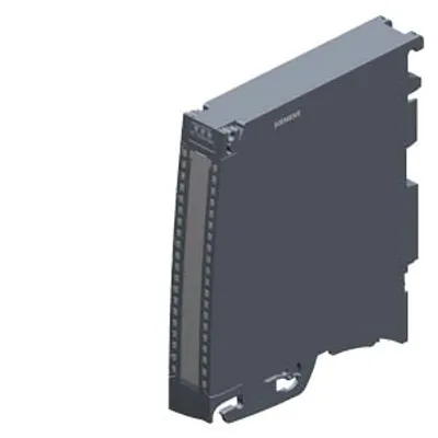

Siemens 6ES7531-7TF00-0AB0Price and lead time confirmed within 1 business day
Request a Quote