























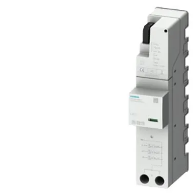
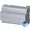
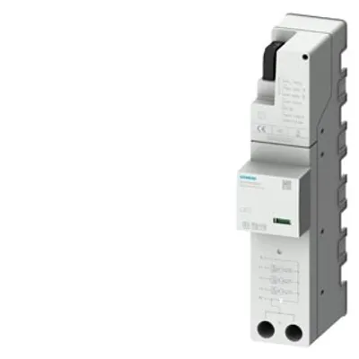
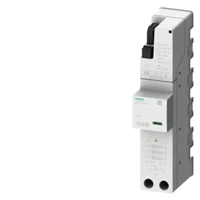
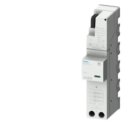
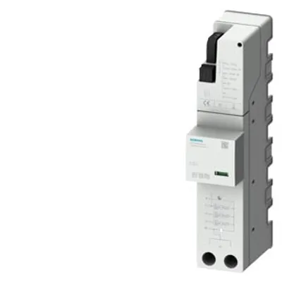
Siemens 5SD7444-1
Combination arrester type 1+2 requirement class B+C, Uc 350 V, protective modules, plug-in, 4-pole
- MPN
- 5SD7444-1
- Category
- Basic devices
Price and lead time confirmed within 1 business day
Request a Quote
- 1We check stock, condition and lead time
- 2You get a written quote by email
- 3Approve it and we ship — in-stock parts within 1 business day
- 12-month warranty (new) · 3-month (used/refurbished)
- 30-day returns, no restocking fee on unused parts
- 100% positive eBay feedback
- Ships via



What is the Siemens 5SD7444-1?
combination arrester type 1+2 requirement class B+C, Uc 350 V, protective modules, plug-in, 4-pole, 3+1 circuit for TN-S and TT systems, with remote display
Specifications
General data
| standard | IEC 61643-11: 2011, EN 61643-11: 2012 |
| product designation | Surge protection device |
| SPD classification according to EN 61643-11 — Test Class I, Type 1 | Yes |
| SPD classification according to EN 61643-11 — Test Class II, Type 2 | Yes |
| SPD classification according to EN 61643-11 — Test Class III, Type 3 | No |
| number of SPD ports | 1 |
| design of the product | Arrester combination |
| design of pole | 3+N/PE |
| designation of the protective paths | L-N, L-PE, N-PE |
| accessories | 3 x 5SD7428-1 + 1 x 5SD7418-0 + 3 x 5SD7448-1 |
| fastening method | TH35 DIN rail |
| material of the enclosure | PBT |
| degree of pollution | 2 |
| overvoltage category according to IEC 61010-1 | III |
| protection class IP at connection all terminals | IP20 |
| shock acceleration | 25 gn |
| vibrational acceleration at 5 Hz ... 500 Hz limited to 2,5 h per axis | 5 gn |
| relative humidity during operation | 5 ... 95 % |
| installation altitude at height above sea level maximum | 2 000 m |
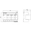
| width | 142.8 mm |
| height | 95 mm |
| depth | 71.5 mm |
Electrical data
| type of distribution system | TN-S, TT |
| operating voltage — at AC | 230 V |
| value range of the operating frequency | 50 / 60 Hz |
| continuous operating voltage — at AC maximum | 350 V |
| continuous operating voltage — between N and PE at AC maximum | 350 V |
| continuous operating voltage — between L and (PE)N at AC maximum | 350 V |
| apparent power consumption maximum | 300 mVA |
| discharge current — between L and (PE)N at (8/20) µs | 25 kA |
| discharge current — between L and PE at (8/20) µs | 25 kA |
| discharge current — between N and PE at (8/20) µs | 100 kA |
| lightning current peak value at (10/350) µs — lightning current peak value between L and PE | 25 kA |
| lightning current peak value at (10/350) µs — lightning current peak value between N and PE | 100 kA |
| lightning current peak value at (10/350) µs — lightning current peak value between L and N | 25 kA |
| charge of the flash at (10/350) µs — charge of the flash between L and N | 12.5 A·s |
| charge of the flash at (10/350) µs — charge of the flash between L and PE | 12.5 A·s |
| charge of the flash at (10/350) µs — charge of the flash between N and PE | 50 A·s |
| specific energy of the flash at (10/350) µs — between L and N | 160 kJ/? |
| specific energy of the flash at (10/350) µs — between L and PE | 160 kJ/? |
| specific energy of the flash at (10/350) µs — between N and PE | 2 500 kJ/? |
| follow current extinguishing capability — between N and PE | 100 A (350 V AC) |
| follow current extinguishing capability — between L and N | 25 kA (264 V AC), 3 kA (350 V AC) |
| short-circuit rating (SCCR) at 264 V | 25 kA |
| protection level — between L and N maximum | 1.5 kV |
| protection level — between L and PE maximum | 2.2 kV |
| protection level — between N and PE maximum | 1.5 kV |
| residual voltage — between L and (PE)N — at rated value of discharge current maximum | 1.5 kV |
| residual voltage — between L and (PE)N — at 10 kA maximum | 1.2 kV |
| residual voltage — between L and (PE)N — at 5 kA maximum | 1 kV |
| residual voltage — between L and (PE)N — at 3 kA maximum | 0.9 kV |
| residual voltage — between L and PE — at rated value of discharge current maximum | 2.2 kV |
| residual voltage — between L and PE — at 10 kA maximum | 2 kV |
| residual voltage — between L and PE — at 5 kA maximum | 1.8 kV |
| residual voltage — between L and PE — at 3 kA maximum | 1.6 kV |
| residual voltage — between N and PE — at rated value of discharge current maximum | 1.5 kV |
| residual voltage — between N and PE — at 10 kA maximum | 1 kV |
| residual voltage — between N and PE — at 5 kA maximum | 0.9 kV |
| residual voltage — between N and PE — at 3 kA maximum | 0.8 kV |
| response value of the surge voltage at 6 kV at (1.2/50) µs — between L and N | 1.5 kV |
| response value of the surge voltage at 6 kV at (1.2/50) µs — between L and PE | 2.2 kV |
| response value of the surge voltage at 6 kV at (1.2/50) µs — between N and PE | 1.5 kV |
| response time between L and (PE)N | 25 ns |
| response time between N and PE | 100 ns |
| adjustable response factor of tripping current | 1.6 |
| fuse protection type at V-shaped connection | 125 A AC (gG) |
| fuse protection type for T-connector | 315 A AC (gG) |
Connections/ Terminals
| type of electrical connection | Screw terminal |
| stripped length | 18 mm |
| tightening torque | 4.3 ... 4.7 N·m |
| connectable conductor cross-section — for finely stranded conductor | 2.5 ... 25 mm² |
| connectable conductor cross-section — for rigid conductor | 2.5 ... 35 mm² |
| connectable conductor cross-section — finely stranded | 2.5 ... 25 mm² |
| AWG number as coded connectable conductor cross section | 13 ... 2 |
| design of the thread of the connection screw | M5 |
| signal design | Optical, remote signaling contact |
Indicator/remote signaling
| product component remote signaling contact | Yes |
| switching function of the remote signaling contacts | PDT contact |
| operating voltage of the remote signaling contacts at AC | 12 ... 250 V |
| operational current of the remote signaling contacts at AC | 10 mA ... 1 A |
| connection type of remote signaling contact | M2 screw thread |
| connectable conductor cross-section for remote signaling contacts for rigid conductor | 0.14 ... 1.5 mm² |
| connectable conductor cross-section for remote signaling contacts for finely stranded conductor | 0.14 ... 1.5 mm² |
| AWG number as coded connectable conductor cross section for remote signaling contacts | 28 ... 16 |
| tightening torque for remote signaling contacts | 0.25 N·m |
| stripped length of the cable for remote signaling contacts | 7 mm |
NEMA/UL - Data
| type of surge protective device (SPD) according to UL | 4CA |
| type of distribution system according to UL | 3Y |
| type of distribution system | TN-S, TT |
| designation of the protective paths according to UL | L-L, L-N, L-G, N-G |
| Measured Limiting Voltage (MLV) — between L and L | 2.47 kV |
| Measured Limiting Voltage (MLV) — between L and Ground (GND) | 1.55 kV |
| Measured Limiting Voltage (MLV) — between L and N | 1.34 kV |
| Measured Limiting Voltage (MLV) — between N and Ground (GND) | 1.08 kV |
| Maximum Continuous Operating Voltage (MCOV) — between L and L | 528 V |
| Maximum Continuous Operating Voltage (MCOV) — between L and Ground (GND) | 528 V |
| Maximum Continuous Operating Voltage (MCOV) — between L and N | 264 V |
| Maximum Continuous Operating Voltage (MCOV) — between N and Ground (GND) | 264 V |
| discharge current — between N and Ground (GND) according to UL rated value | 20 kA |
| discharge current — between L and N according to UL rated value | 20 kA |
| discharge current — between L and Ground (GND) according to UL rated value | 20 kA |
| discharge current — between L and L according to UL rated value | 20 kA |
| AWG number as coded connectable conductor cross section — according to UL | 12 ... 2 |
| AWG number as coded connectable conductor cross section — for remote signaling contacts according to UL | 30 ... 14 |
| operating voltage of the remote signaling contacts according to UL | 125 V |
| operational current of the remote signaling contacts at AC according to UL | 1 A |
| ambient temperature — during operation | -40 ... +80 °C |
| ambient temperature — during storage | -40 ... +80 °C |
| installation altitude above sea level according to UL | 6 562 ft |
| combustibility class according to UL 94 | V0 |
| standards according to UL | UL 1449 edition 4 |
No matching specifications
Downloads & documentation
Official documents from Siemens, downloaded directly from the manufacturer.
Data sheets & manuals
5SD7444-1: frequently asked questions
When can 5SD7444-1 be shipped?
5SD7444-1 is sourced on request — request a quote and we'll confirm the exact availability and shipping timeline for this specific unit.
Can I pick up 5SD7444-1 in person?
Local pickup from our Groningen, Netherlands warehouse may be possible — contact us before ordering to check availability and arrange a collection time.
Is express delivery available?
Yes — mention it when you request a quote for 5SD7444-1 and we'll include express shipping options in our reply.
My factory is down and I need this urgently — can you help?
For a critical breakdown, contact us directly at +31 (0)50-7110348 or sales@partnerplc.com — we can look into same-day courier or dedicated taxi/hotshot delivery for 5SD7444-1, subject to availability and destination.
More Siemens parts
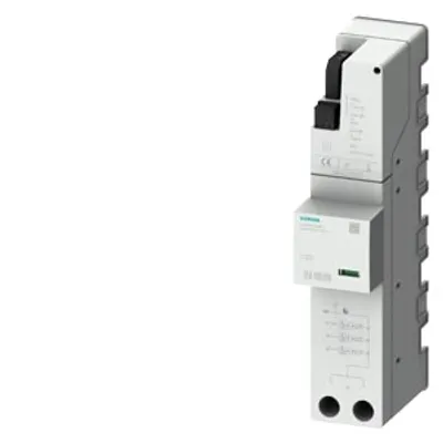
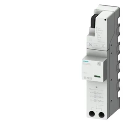
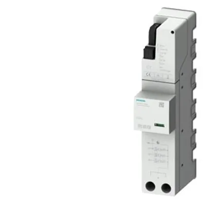
Siemens 5SD7444-1Price and lead time confirmed within 1 business day
Request a Quote