


Pepperl Fuchs R2-SP-IC*
Request a Quote



Quick facts
| Availability | Confirmed on request |
| Category | Segment Protectors |
| Lifecycle | active |
| Warranty | 12-month (new) · 3-month (used/refurbished) |
Shipping & availability
When can R2-SP-IC* be shipped?
R2-SP-IC* is sourced on request — request a quote and we'll confirm the exact availability and shipping timeline for this specific unit.
Can I pick up R2-SP-IC* in person?
Local pickup from our Groningen, Netherlands warehouse may be possible — contact us before ordering to check availability and arrange a collection time.
Is express delivery available?
Yes — mention it when you request a quote for R2-SP-IC* and we'll include express shipping options in our reply.
My factory is down and I need this urgently — can you help?
For a critical breakdown, contact us directly at +31 (0)50-7110348 or sales@partnerplc.com — we can look into same-day courier or dedicated taxi/hotshot delivery for R2-SP-IC*, subject to availability and destination.
Segment Protector. Segment protector, junction box for fieldbus with short-circuit and fault protection, field junction box, electronic component for control cabinet installation, 4 ... 12 outputs Ex ic (FISCO or Entity) or non-incendive (Div 2), Advanced fault isolation at the spur, Segment Protector in Zone 2/Div. 2, Instruments in Zone 2/Div. 2 or Zone 1/Div. 1, For FOUNDATION Fieldbus H1 and PROFIBUS PA, IECEx approval, International, Europe, USA, Canada. Design / Mounting: Cabinet installation. Installation in hazardous area: Zone 2 / Div. 2. Main cable (Trunk): . Rated voltage9 ... 31 V DC10.5 V DC minimum input voltage acc. to FF-846Rated currentmax. 4.5 A: . Rated voltage: 9 ... 31 V DC10.5 V DC minimum input voltage acc. to FF-846. Rated current: max. 4.5 A. Outputs: . Number of outputssee table "Technical data depending on model"Number of devices per output1Rated voltagemax. 31 VRated currentmax. 32 mA switch 1, position 1 max. 43 mA switch 1, position 2Short-circuit current46 mA switch 1, position 1 57 mA switch 1, position 2: . Number of outputs: see table "Technical data depending on model". Number of devices per output: 1. Rated voltage: max. 31 V. Rated current: max. 32 mA switch 1, position 1 max. 43 mA switch 1, position 2. Short-circuit current: 46 mA switch 1, position 1 57 mA switch 1, position 2. Self current consumption: see table "Technical data depending on model". Voltage drop main cable/outputs: max. 1.2 V. Voltage drop trunk In/Out: 0 V. Terminating resistor: external type M-FT 100 Ω +/- 10 %. Surge protection: Trunk overvoltage protection if voltage exceeds typ. 39 V, max. 41 V. Switch: configuration of short-circuit current/rated current. LED PWR: green: Fieldbus voltage > 10 V and fieldbus terminator is deactivated. LED COM/ERR: yellow: flashing: fieldbus communication status and physical layer diagnostic status. LED SPURS: red: 2 Hz flashing in short-circuit condition. Electromagnetic compatibility: . Directive 2014/30/EUEN 61326-1:2013: . Directive 2014/30/EU: EN 61326-1:2013. Electromagnetic compatibility: NE 21:2011. Degree of protection: IEC 60529. Fieldbus standard: IEC 61158-2. Climatic conditions: IEC 60721. Shock resistance: EN 60068-2-27. Vibration resistance: EN 60068-2-6. Ambient temperature: -50 ... 70 °C (-58 ... 158 °F). Storage temperature: -50 ... 85 °C (-58 ... 185 °F). Relative humidity: < 95 % non-condensing. Shock resistance: 15 g 11 ms. Vibration resistance: 1 g , 10 ... 150 Hz. Corrosion resistance: acc. to ISA-S71.04-1985, severity level G3. Connection type: screw terminal , pluggable or spring terminal , pluggable. Core cross section: see table 2. Housing material: Polycarbonate. Degree of protection: IP20. Mass: see table "Technical data depending on model". Dimensions: see table "Technical data depending on model". Mounting: DIN rail mounting. EU-type examination certificate: TÜV 12 ATEX 098651 X. Marking II 3G Ex nA [ic] IIC T4 Gc [exsign] II (3)D [Ex ic Dc] IIIC: . Marking: II 3G Ex nA [ic] IIC T4 Gc [exsign] II (3)D [Ex ic Dc] IIIC. Supply: . Maximum safe voltageUm35 V: Um. Maximum safe voltage: 35 V. Outputs: . VoltageUo32 VCurrentIo46 mA switch 1, position 1 65 mA switch 1, position 2InductanceLo0.125 mH switch 1, position 1 0.25 mH switch 1, position 2CapacitanceCo60 nF: Uo. Voltage: 32 V. Current: 46 mA switch 1, position 1 65 mA switch 1, position 2. Inductance: 0.125 mH switch 1, position 1 0.25 mH switch 1, position 2. Capacitance: 60 nF. Directive conformity: . Directive 2014/34/EUEN IEC 60079-0:2018+AC:2020 , EN 60079-11:2012 , EN 60079-15:2010: . Directive 2014/34/EU: EN IEC 60079-0:2018+AC:2020 , EN 60079-11:2012 , EN 60079-15:2010. UL approval: E106378. Control drawing116-0406Approved forClass I, Division 2, Groups A, B, C, D: . Control drawing: 116-0406. Approved for: Class I, Division 2, Groups A, B, C, D. IECEx approval: . IECEx certificateIECEx TUN 12.0015XIECEx markingEx nA [ic] IIC T4 Gc [Ex ic Dc] IIIC: . IECEx certificate: IECEx TUN 12.0015X. IECEx marking: Ex nA [ic] IIC T4 Gc [Ex ic Dc] IIIC. Supplementary information: Statement of Conformity, Declaration of Conformity, Attestation of Conformity and instructions have to be observed where applicable. For information see www.pepperl-fuchs.com.
Specifications
General specifications
| Design / Mounting | Cabinet installation |
| Installation in hazardous area | Zone 2 / Div. 2 |
Fieldbus connection
| Main cable (Trunk) | |
| Rated voltage9 ... 31 V DC10.5 V DC minimum input voltage acc. to FF-846Rated currentmax. 4.5 A | Rated voltage |
| Rated voltage | 9 ... 31 V DC10.5 V DC minimum input voltage acc. to FF-846 |
| Rated current | max. 4.5 A |
| Outputs | |
| Number of outputssee table "Technical data depending on model"Number of devices per output1Rated voltagemax. 31 VRated currentmax. 32 mA switch 1, position 1 max. 43 mA switch 1, position 2Short-circuit current46 mA switch 1, position 1 57 mA switch 1, position 2 | Number of outputs |
| Number of outputs | see table "Technical data depending on model" |
| Number of devices per output | 1 |
| Rated voltage | max. 31 V |
| Rated current | max. 32 mA switch 1, position 1 max. 43 mA switch 1, position 2 |
| Short-circuit current | 46 mA switch 1, position 1 57 mA switch 1, position 2 |
| Self current consumption | see table "Technical data depending on model" |
| Voltage drop main cable/outputs | max. 1.2 V |
| Voltage drop trunk In/Out | 0 V |
| Terminating resistor | external type M-FT 100 Ω +/- 10 % |
| Surge protection | Trunk overvoltage protection if voltage exceeds typ. 39 V, max. 41 V |
Indicators/operating means
| Switch | configuration of short-circuit current/rated current |
| LED PWR | green: Fieldbus voltage > 10 V and fieldbus terminator is deactivated |
| LED COM/ERR | yellow: flashing: fieldbus communication status and physical layer diagnostic status |
| LED SPURS | red: 2 Hz flashing in short-circuit condition |
Directive conformity
| Electromagnetic compatibility | |
| Directive 2014/30/EUEN 61326-1:2013 | Directive 2014/30/EU |
| Directive 2014/30/EU | EN 61326-1:2013 |
Standard conformity
| Electromagnetic compatibility | NE 21:2011 |
| Degree of protection | IEC 60529 |
| Fieldbus standard | IEC 61158-2 |
| Climatic conditions | IEC 60721 |
| Shock resistance | EN 60068-2-27 |
| Vibration resistance | EN 60068-2-6 |
Ambient conditions
| Ambient temperature | -50 ... 70 °C (-58 ... 158 °F) |
| Storage temperature | -50 ... 85 °C (-58 ... 185 °F) |
| Relative humidity | < 95 % non-condensing |
| Shock resistance | 15 g 11 ms |
| Vibration resistance | 1 g , 10 ... 150 Hz |
| Corrosion resistance | acc. to ISA-S71.04-1985, severity level G3 |
Mechanical specifications
| Connection type | screw terminal , pluggable or spring terminal , pluggable |
| Core cross section | see table 2 |
| Housing material | Polycarbonate |
| Degree of protection | IP20 |
| Mass | see table "Technical data depending on model" |
| Dimensions | see table "Technical data depending on model" |
| Mounting | DIN rail mounting |
Data for application in connection with hazardous areas
| EU-type examination certificate | TÜV 12 ATEX 098651 X |
| Marking II 3G Ex nA [ic] IIC T4 Gc [exsign] II (3)D [Ex ic Dc] IIIC | Marking |
| Marking | II 3G Ex nA [ic] IIC T4 Gc [exsign] II (3)D [Ex ic Dc] IIIC |
| Supply | |
| Maximum safe voltageUm35 V | Um Maximum safe voltage |
| Maximum safe voltage | 35 V Um |
| Outputs | |
| VoltageUo32 VCurrentIo46 mA switch 1, position 1 65 mA switch 1, position 2InductanceLo0.125 mH switch 1, position 1 0.25 mH switch 1, position 2CapacitanceCo60 nF | Uo Voltage |
| Voltage | 32 V Uo |
| Current | 46 mA switch 1, position 1 65 mA switch 1, position 2 Io |
| Inductance | 0.125 mH switch 1, position 1 0.25 mH switch 1, position 2 Lo |
| Capacitance | 60 nF Co |
| Directive conformity | |
| Directive 2014/34/EUEN IEC 60079-0:2018+AC:2020 , EN 60079-11:2012 , EN 60079-15:2010 | Directive 2014/34/EU |
| Directive 2014/34/EU | EN IEC 60079-0:2018+AC:2020 , EN 60079-11:2012 , EN 60079-15:2010 |
International approvals
| UL approval | E106378 |
| Control drawing116-0406Approved forClass I, Division 2, Groups A, B, C, D | Control drawing |
| Control drawing | 116-0406 |
| Approved for | Class I, Division 2, Groups A, B, C, D |
| IECEx approval | |
| IECEx certificateIECEx TUN 12.0015XIECEx markingEx nA [ic] IIC T4 Gc [Ex ic Dc] IIIC | IECEx certificate |
| IECEx certificate | IECEx TUN 12.0015X |
| IECEx marking | Ex nA [ic] IIC T4 Gc [Ex ic Dc] IIIC |
General information
| Supplementary information | Statement of Conformity, Declaration of Conformity, Attestation of Conformity and instructions have to be observed where applicable. For information see www.pepperl-fuchs.com. |
More Pepperl Fuchs parts
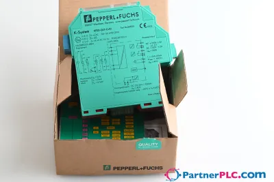 NewPepperl + Fuchs KFD2-GUT-EX1.D New open box
 Available on requestPepperl Fuchs V19-W-BK15M-PUR-U-V19-G
 Available on requestPepperl Fuchs V1SD-G-GN65M-PUR-E1S-V45-G