























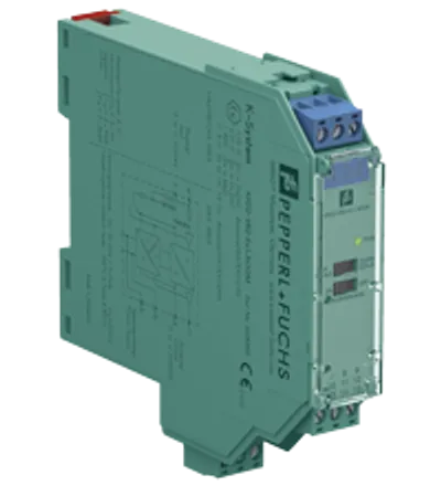
Pepperl Fuchs KFD2-WAC2-Ex1.D
Strain Gauge Converter
- MPN
- KFD2-WAC2-Ex1.D
- Category
- K-System (DIN Rail Mounting)
Price and lead time confirmed within 1 business day
Request a Quote
- 1We check stock, condition and lead time
- 2You get a written quote by email
- 3Approve it and we ship — in-stock parts within 1 business day
- 12-month warranty (new) · 3-month (used/refurbished)
- 30-day returns, no restocking fee on unused parts
- 100% positive eBay feedback
- Ships via



What is the Pepperl Fuchs KFD2-WAC2-Ex1.D?
1-channel isolated barrier
24 V DC supply (Power Rail)
Strain gauge input (full or half bridge)
Output 0 mA ... ± 20 mA or 0 V ... ± 10 V
2 relay contact outputs
Programmable high/low alarm
Configurable by PACTware or keypad
RS-485 interface
Line fault detection (LFD)
1-channel isolated barrier, 24 V DC supply (Power Rail), Strain gauge input (full or half bridge), Output 0 mA ... ± 20 mA or 0 V ... ± 10 V, 2 relay contact outputs, Programmable high/low alarm, Configurable by PACTware or keypad, RS-485 interface, Line fault detection (LFD), Housing width: 40 mm, Number of channels: 1-channel, Trip relay, Rated voltage: 20 ... 35 V DC, Field device: strain gauge bridge, Type: 2 x relay (change-over contact), Signal: 1 x -20 ... 20 mA
Specifications
General specifications
| Order code (Pepperl+Fuchs part number) | 231221 |
| Signal type | Analog input |
| Lifecycle | Active (current Pepperl+Fuchs product) |
Supply
| Connection | Power Rail or terminals 23+, 24- |
| Rated voltage | 20 ... 35 V DC Ur |
| Ripple | within the supply tolerance |
| Power consumption | max. 3 W |
Interface
| Connection | Power Rail or terminals 19+, 20 GND, 21- |
| Type | RS-485 |
| Programming interface | programming socket |
Field circuit
| Connection | terminals 1+, 2-, 3+, 4-, 5+, 6- |
| Lead resistance | max. 25 Ω per line |
| Input I: Connection | terminals 1+, 2- |
| Sensor supply | 1 ... 5 V |
| Connection | terminals 3+, 4- (supply); 5+, 6- (signal) |
| Short-circuit current | 50 mA |
| Load | ≥ 116 Ω up to 5V, ≥ 85 Ω up to 4V |
Input
| Connection side | field side |
| Connection | Input I: terminals 1+, 2-; Input II: terminals 13+, 14-; Input III: terminals 15+, 14- |
| Programmable Tare | 0 ... 500 % of span |
| Input I | Signal, analog |
| Input signal | -100 ... 100 mV |
| Input resistance | > 1 MΩ for voltage measurement |
| Input II, III | tare adjustment, calibration and zero |
| Open circuit voltage/short-circuit current | 18 V / 5 mA |
| Active/Passive | I > 4 mA/I < 1.5 mA |
Output
| Connection side | control side |
| Connection | Output I: terminals 10, 11, 12; Output II: terminals 16, 17, 18; Output III: terminals 7-, 8+, 9- |
| Output I, II | Relay output |
| Contact loading | 253 V AC/2 A/500 VA/cos φ min. 0.7; 40 V DC/2 A resistive load |
| Mechanical life | 2 x 10⁷ switching cycles |
| Output III | Analog output |
| Current range | -20 ... 20 mA |
| Load | max. 550 Ω |
| Analog voltage output | 0 ... ± 10 V; output resistance 500 Ω (bridge between terminal 7 and 9) |
| Analog current output | 0 ... ± 20 mA or 4 ... 20 mA; load 0 ... 550 Ω (terminals 7 and 8) |
| Line fault detection | downscale -21.5 mA (-10.75 V) or 2 mA (1 V), upscale 21.5 mA (10.75 V) |
| Collective error message | Power Rail |
Transfer characteristics
| Deviation: Resolution/accuracy | ≤ ± 0.05 % incl. non-linearity and hysteresis |
| Deviation: Temperature effect | ≤ ± 0.01 %/K |
| Reaction time | 300 ... 850 ms |
Galvanic isolation
| Input I/other circuits | reinforced insulation according to IEC/EN 61010-1, rated insulation voltage 300 Veff |
| Output I, II against eachother | reinforced insulation according to IEC/EN 61010-1, rated insulation voltage 300 Veff |
| Output I, II/other circuits | reinforced insulation according to IEC/EN 61010-1, rated insulation voltage 300 Veff |
| Output III/Input II, III | not available |
| Output III/Programming socket | not available |
| Other circuits from each other | functional insulation, rated insulation voltage 50 Veff |
Indicators/settings
| Display elements | LEDs , display |
| Control elements | Control panel |
| Configuration | via operating buttons via PACTware |
| Labeling | space for labeling at the front |
Directive conformity
| Electromagnetic compatibility: Directive 2014/30/EU | EN 61326-1:2013 (industrial locations) |
| Low voltage: Directive 2014/35/EU | EN 61010-1:2010 |
Conformity
| Electromagnetic compatibility | NE 21:2006 |
| Degree of protection | IEC 60529:2001 |
Ambient conditions
| Ambient temperature | -20 ... 60 °C (-4 ... 140 °F) |
Mechanical specifications
| Degree of protection | IP20 |
| Connection | screw terminals |
| Mass | approx. 250 g |
| Dimensions | 40 x 119 x 115 mm (1.6 x 4.7 x 4.5 inch) (W x H x D) , housing type C2 |
| Height | 119 mm |
| Width | 40 mm |
| Depth | 115 mm |
| Mounting | on 35 mm DIN mounting rail acc. to EN 60715:2001 |
Data for application in connection with hazardous areas
| EU-type examination certificate | TÜV 04 ATEX 2531 |
| Marking | II (1)G [Ex ia Ga] IIC [exsign] II (1)D [Ex ia Da] IIIC [exsign] I (M1) [Ex ia Ma] I |
| Supply | Power Rail or terminals 23+, 24- non-intrinsically safe |
| Maximum safe voltage | 40 V DC (Attention! Um is no rated voltage.) Um |
| Input I | terminals 1+, 2- Ex ia IIC, Ex iaD |
| Voltage Uo | 14 V |
| Current Io | 238 mA |
| Power Po | 833 mW (linear characteristic) |
| Input II and III | terminals 13+, 14-; 15+, 14- non-intrinsically safe |
| Maximum safe voltage Um | 40 V DC (Attention! Um is no rated voltage.) |
| Output I, II | terminals 10, 11, 12; 16, 17, 18 non-intrinsically safe |
| Maximum safe voltage | 253 V AC / 40 V DC (Attention! Um is no rated voltage.) Um |
| Contact loading | 253 V AC/2 A/500 VA/cos φ min. 0.7; 40 V DC/2 A resistive load |
| Output III | terminals 7-, 8+, 9- non-intrinsically safe |
| Maximum safe voltage Um | 40 V DC (Attention! Um is no rated voltage.) Um |
| Interface | RS 485 programming jack |
| Maximum safe voltage | 40 V DC (Attention! Um is no rated voltage.) Um |
| Galvanic isolation: Input I/other circuits | safe electrical isolation acc. to IEC/EN 60079-11, voltage peak value 375 V |
| Directive conformity: Directive 2014/34/EU | EN 60079-0:2012+A11:2013 , EN 60079-11:2012 |
International approvals
| FM approval: Control drawing | 116-0302 (cFMus) |
| UL approval | E223772 |
| IECEx approval: IECEx certificate | IECEx TUN 06.0005 |
| IECEx approval: IECEx marking | [Ex ia Ga] IIC , [Ex ia Da] IIIC , [Ex ia Ma] I |
General information
| Supplementary information | Observe the certificates, declarations of conformity, instruction manuals, and manuals where applicable. For information see www.pepperl-fuchs.com. |
No matching specifications
Downloads & documentation
Official documents from Pepperl Fuchs, downloaded directly from the manufacturer.
Data sheets & manuals
CAD & dimension drawings
Certificates (8)
- China SITIIAS CCC Ex Certificate (2021322316004119 (Singapore))
- EU Declaration of Conformity (Pepperl+Fuchs)
- South Africa MASC (MASC MS/17-0878)
- United Kingdom CML UK-Type Examination Certificate UKEX Category (1) D UKEX Category (1) G UKEX Category (M1) (CML 22UKEX2504)
- Korea KOSHA (19-AV4BO-0392)
- Australia Test Safe (ANZEx 22.3012)
- Europe TUV Nord ATEX Category (1) D ATEX Category (1) G ATEX Category (M1) (TÜV 04 ATEX 2531)
- Canada FM (FM 18 CA 0121X)
KFD2-WAC2-Ex1.D: frequently asked questions
When can KFD2-WAC2-Ex1.D be shipped?
KFD2-WAC2-Ex1.D is sourced on request — request a quote and we'll confirm the exact availability and shipping timeline for this specific unit.
Can I pick up KFD2-WAC2-Ex1.D in person?
Local pickup from our Groningen, Netherlands warehouse may be possible — contact us before ordering to check availability and arrange a collection time.
Is express delivery available?
Yes — mention it when you request a quote for KFD2-WAC2-Ex1.D and we'll include express shipping options in our reply.
My factory is down and I need this urgently — can you help?
For a critical breakdown, contact us directly at +31 (0)50-7110348 or sales@partnerplc.com — we can look into same-day courier or dedicated taxi/hotshot delivery for KFD2-WAC2-Ex1.D, subject to availability and destination.
More Pepperl Fuchs parts
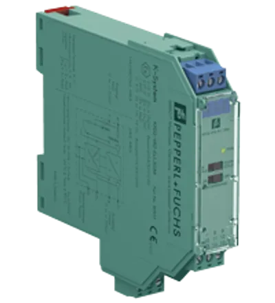
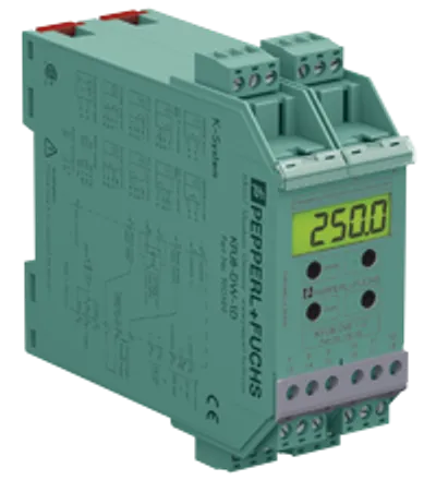
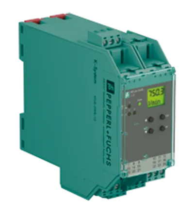
Pepperl Fuchs KFD2-WAC2-Ex1.DPrice and lead time confirmed within 1 business day
Request a Quote