



.svg&w=240)


















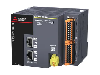
MXF100S-16-N32 Mitsubishi MELSEC MX Controller
Request a Quote



Quick facts
| Availability | Confirmed on request |
| Category | Mitsubishi MELSEC MX Controller – Controller |
| Lifecycle | Active |
| Warranty | 12-month (new) · 3-month (used/refurbished) |
Shipping & availability
When can MXF100S-16-N32 be shipped?
MXF100S-16-N32 is sourced on request — request a quote and we'll confirm the exact availability and shipping timeline for this specific unit.
Can I pick up MXF100S-16-N32 in person?
Local pickup from our Groningen, Netherlands warehouse may be possible — contact us before ordering to check availability and arrange a collection time.
Is express delivery available?
Yes — mention it when you request a quote for MXF100S-16-N32 and we'll include express shipping options in our reply.
My factory is down and I need this urgently — can you help?
For a critical breakdown, contact us directly at +31 (0)50-7110348 or sales@partnerplc.com — we can look into same-day courier or dedicated taxi/hotshot delivery for MXF100S-16-N32, subject to availability and destination.
The Mitsubishi Electric MXF100S-16-N32 is a controller in the MELSEC MX Controller. Program memory (standard): 30 MB Program memory (safety): 6 MB Maximum number of controllable axes: 16 axes Built-in CC-Link IE TSN (with Safety Functions) Input (standard): 16 points Output (standard): 16 points transistor (sink). Specifications and manuals below are Mitsubishi Electric's own data.
Specifications
Product
| Series | MELSEC MX Controller |
| Outline | Program memory (standard): 30 MB Program memory (safety): 6 MB Maximum number of controllable axes: 16 axes Built-in CC-Link IE TSN (with Safety Functions) Input (standard): 16 points Output (standard): 16 points transistor (sink) |
Specifications
| Operation control method | Repetitive operation of stored programs |
| I/O control mode | Refresh mode (The direct access input/output is available by specifying the direct access input/output (DX, DY).) |
| Programming language | • Ladder diagram (LD) • Structured text (ST) • Function block diagram (FBD/LD) |
| Extended programming language | • Function block (FB) • Label programming |
| Program execution type | Initial, scan, fixed scan, interrupt, and standby |
| Number of I/O points | 512 points |
| Memory capacity: Program memory | • Standard: 30 MB • Safety: 6 MB |
| Memory capacity: Program cache memory | • Standard: 12 MB • Safety: 2 MB |
| Memory capacity: Device/label memory | • Standard: 8192 KB • Safety: 80 KB |
| Memory capacity: Data memory | 15 MB |
| Online change | Supported (standard program only) |
| Processing speed: Instruction processing time: LD instruction | • Standard control: 1.25 ns • Safety control: 124 ns |
| Number of occupied I/O points | Not supported |
| Number of slots occupied by a module | Not supported |
Peripheral connection port
| USB port | USB 2.0 High Speed (Type-C) × 1 |
| Ethernet port | One of the CC-Link IE TSN ports can be switched to the Ethernet port. |
| CC-Link IE TSN port | 1000BASE-T/100BASE-TX × 2 One of the CC-Link IE TSN ports can be switched to the Ethernet port. |
Memory interface
| SD memory card | SD/SDHC memory card |
Motion control specifications
| Number of controllable axes: Real drive axis | 16 axes |
| Motion operation cycle [μs] | 250, 500, 1000, 1500, 2000, 2500, 3000, 3500, 4000, 4500, 5000, 5500, 6000, 6500, 7000, 7500, 8000 |
| Servo amplifier connection | MR-J5-G, MR-J5W2-G, MR-J5W3-G, MR-J5D1-G4, MR-J5D2-G4, MR-J5D3-G4, CC-Link IE TSN-compatible drive, MR-JET |
| Absolute position control system | 64 bit control/32 bit control |
| Positioning range | 64 bit floating-point (LREAL type) |
| Interpolation function | Linear interpolation (4 axes maximum), 2-axis circular interpolation |
| Control method | PTP control, speed control, speed-position switching control (future support), speed control/torque control/continuous operation to torque control, pressure control (future support), multi-axis positioning data operation, position follow-up control, and motion cyclic instruction (position, velocity, and torque) |
| Operation cycles mixed | 3 groups |
| System memory size | 96 MB |
| Size of built-in ROM for user data | 15 MB (Data memory is used.) |
| Axis | Real drive axis, virtual drive axis, real encoder axis, virtual encoder axis, and virtual linked axis |
| Axis: Axes group | 0: Not set 1…: Setting axes group No. |
| Axis: Real drive axis | Servo amplifier |
| Axis: Real encoder axis | Via a servo amplifier |
| Compensation function | Driver unit conversion function and phase compensation function (future support) |
| Synchronous control: Instruction | Advanced synchronous control and cam operation start (MC_Camln) |
| Synchronous control: Module | Master axis, cam, gear, and clutch |
| Synchronous control: Master axis | Real drive axis, virtual drive axis, real encoder axis, virtual encoder axis, and virtual linked axis |
| Start/stop | Start, stop, restart, buffer mode, and forced stop |
| Home position return: Home position return method | Driver home position return method (use the home position return method set in the driver) |
| Positional control: Linear control | Linear interpolation (2…4 axes) |
| Positional control: 2-axis circular interpolation | Border point specification, center point specification, and radius specification |
| Manual control | JOG operation |
| Direct control: Speed control | Speed control not including position loop and speed control including position loop |
| Direct control: Torque control | Torque control and continuous operation to torque control |
| Absolute positioning system | Provided (batteryless) |
| Function to limit control: Velocity limit | Velocity set range |
| Function to limit control: Torque limit | Positive direction torque limit value, negative direction torque limit value |
| Function to limit control: Forced stop | Enabled/disabled switching |
| Function to limit control: Software stroke limit | Check the movable range at the set position and the machine feed value. |
| Function to limit control: Hardware stroke limit | Supported |
| Function to change control content: Set velocity change | Supported |
| Function to change control content: Current value change | Supported |
| Function to change control content: Acceleration/deceleration process change | Acceleration/deceleration and acceleration/deceleration time |
| Function to change control content: Torque limit value change | Supported |
| Function to change control content: Target position change | Target position change and movement distance change |
| Function to change control content: Override | Supported |
| Function: History data | Position data history |
| Function: Axis emulation | Supported |
| Function: Touch probe (mark detection) | Supported |
| Function: Monitoring of servo data | Cyclic transmission and transient transmission |
| Function: Servo system recorder | Not supported |
| Function: Digital cam switch | Supported |
Operation profile data (cam) specifications
| Number of registrations | 60000 maximum (settable number from engineering tool: 1024) |
| Cam data: Type | Cam data and rotary knife |
| Cam data: Interpolation method | Specifying for each section, linear interpolation, and spline interpolation |
| Cam data: Profile ID | 1…60000 |
| Cam data: Resolution | 8…65535 (optional) |
| Cam data: Unit of length per cycle setting | mm, inch, pulse, degree |
| Cam data: Unit of stroke amount | %, mm, inch, pulse, degree |
| Cam auto-generation | Cam auto-generation cam for rotary knife |
Network (CC-Link IE TSN) specifications
| Transmission speed | 1 Gbps/100 Mbps |
| Maximum number of connectable stations per network | 47 stations (manager station: 1, device station: 46) |
| Network topology | Line topology, star topology, coexistence of line and star topologies |
| Overall cable length: Line connection | 4600 m (when 47 stations are connected) |
| Overall cable length: Others | Depends on the system configuration. |
| Maximum station-to-station distance | 100 m |
| Maximum number of link points per network: RX/RY | 16K points (16384 points, 2 KB) for each |
| Maximum number of link points per network: RWr/RWw | 8K points (8192 points, 16 KB) for each |
| Maximum number of link points per station: RX/RY | Manager station: 8K points (8192 points, 1 KB) for each |
| Maximum number of link points per station: RWr/RWw | Manager station: 4K points (4096 points, 8 KB) for each |
| Connection cable | Ethernet cable (Category 5e or higher) |
| Communication method | Time sharing method |
| Transient transmission capacity | Maximum 1920 bytes |
Power supply specifications
| Rated voltage *1 | 24 V DC |
| Voltage fluctuation range | +20%, -15% |
| Power fuse | 125 V, 3.15 A time-lag fuse |
| Inrush current | 100 A, 0.06 ms or less 4.0 A, 350 ms or less |
| Power consumption | Controller alone: 25 W or less Maximum configuration for connection to the controller: 45 W or less (external 24 V DC power supply of extension devices is not included) |
| 24 V DC built-in power supply capacity | 500 mA |
| 5 V DC built-in power supply capacity | 720 mA |
Safety specification
| Safety category | Category 4 (EN ISO 13849-1) |
| Performance level (PL) | PL e (EN ISO 13849-1) |
| Safety level (SIL) | SIL 3 (EN 61508) |
Specifications
| Operating ambient temperature *3 | 0…55°C, non-freezing |
| Storage ambient temperature | -40…75°C, non-freezing *4 |
| Operating ambient humidity | 5…95% RH, non-condensing *5 |
| Storage ambient humidity | 5…95% RH, non-condensing |
| Vibration resistance *6: Installed on DIN rail: Frequency: 5…8.4 Hz | Half amplitude: 3.5 mm Number of sweeps: 10 times each in X, Y, and Z directions (total 80 minutes in each direction) |
| Vibration resistance *6: Installed on DIN rail: Frequency: 8.4…150 Hz | Acceleration: 10 m/s 2 Number of sweeps: 10 times each in X, Y, and Z directions (total 80 minutes in each direction) |
| Shock resistance *7 | 150 m/s 2 , Duration of action: 11 ms, 3 times each in X, Y, and Z bidirections by sine half-wave pulse |
| Noise immunity | By noise simulator at noise voltage of 1000 Vp-p, noise width of 1 μs and period of 30…100 Hz |
| Grounding | Grounding resistance of 100Ω or less (Common grounding with a heavy electrical system is not allowed) *8 |
| Operating atmosphere | No corrosive gases and flammable gases, less conductive dust |
| Operating altitude *9 | 0…2000 m |
| Installation location | Inside a control panel *10 |
| Overvoltage category *11 | II or less |
| Pollution degree *12 | 2 or less |
Downloads & documentation
Official documents from Mitsubishi Electric (Factory Automation), downloaded directly from the manufacturer.
Data sheets & manuals
More Mitsubishi Electric (Factory Automation) parts
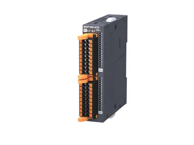 Available on requestMXF100-X32 Mitsubishi MELSEC MX Controller I/O Module
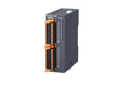 Available on requestMXF100-Y16R Mitsubishi MELSEC MX Controller I/O Module
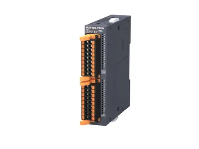 Available on requestMXF100-Y32N Mitsubishi MELSEC MX Controller I/O Module
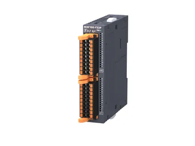 Available on requestMXF100-Y32P Mitsubishi MELSEC MX Controller I/O Module
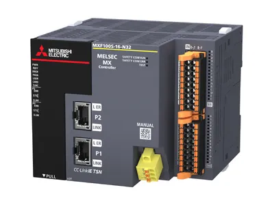 Available on requestMXF100S-16-P32 Mitsubishi MELSEC MX Controller
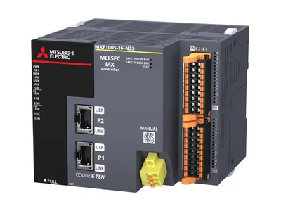 Available on requestMXF100S-8-N32 Mitsubishi MELSEC MX Controller
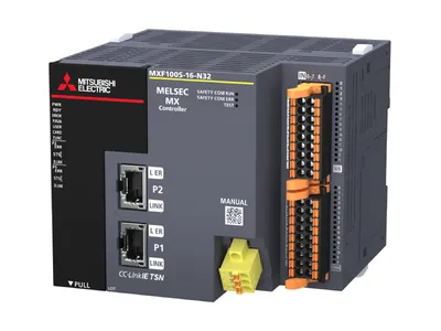 Available on requestMXF100S-8-P32 Mitsubishi MELSEC MX Controller
 Available on requestMXF100S-N32 Mitsubishi MELSEC MX Controller