




.svg&w=240)


















FX5-SF-MU4T5 Mitsubishi MELSEC iQ-F Series Safety Extension Module
Request a Quote



Quick facts
| Availability | Confirmed on request |
| Category | Mitsubishi MELSEC iQ-F Series – Safety Extension Module |
| Lifecycle | Active |
| Warranty | 12-month (new) · 3-month (used/refurbished) |
Shipping & availability
When can FX5-SF-MU4T5 be shipped?
FX5-SF-MU4T5 is sourced on request — request a quote and we'll confirm the exact availability and shipping timeline for this specific unit.
Can I pick up FX5-SF-MU4T5 in person?
Local pickup from our Groningen, Netherlands warehouse may be possible — contact us before ordering to check availability and arrange a collection time.
Is express delivery available?
Yes — mention it when you request a quote for FX5-SF-MU4T5 and we'll include express shipping options in our reply.
My factory is down and I need this urgently — can you help?
For a critical breakdown, contact us directly at +31 (0)50-7110348 or sales@partnerplc.com — we can look into same-day courier or dedicated taxi/hotshot delivery for FX5-SF-MU4T5, subject to availability and destination.
The Mitsubishi Electric FX5-SF-MU4T5 is a safety Extension Module in the MELSEC iQ-F Series. Safety main module Safety inputs: 4 points Safety outputs: 4 points Off delay time 0 to 5 s Spring clamp terminal block type Powered by SICK. Specifications and manuals below are Mitsubishi Electric's own data.
Specifications
Product
| Series | MELSEC iQ-F Series |
| Category | Safety Extension Module |
| Outline | Safety main module Safety inputs: 4 points Safety outputs: 4 points Off delay time 0 to 5 s Spring clamp terminal block type Powered by SICK |
Specifications
| Applicable CPU module | FX5UJ CPU module*1: Ver. 1.010 or later FX5U CPU module*1: Ver. 1.200 or later FX5UC CPU module*1*2: Ver. 1.200 or later *1 Extension modules for general-purpose control cannot be connected after the safety extension module. *2 FX5-CNV-IFC or FX5-C1PS-5V is required to connect to the FX5UC CPU module. |
| Mass (weight) | Approx. 0.3 kg |
| Number of connectable units | FX5UJ/FX5U/FX5UC CPU module: Up to 1 module |
Safety Specifications
| Safety integrity level | SIL3 (IEC 61508)/SILCL 3 (IEC 62061) |
| Category | Category 4 (DIN EN ISO 13849-1) |
| Performance level | PL e (DIN EN ISO 13849-1) |
| PFHd | 1.5 × 10 -9 to 1.5 × 10 -8 |
| TM (mission time) | 20 years (EN ISO 13849-1) |
Performance Specifications
| Safety inputs: No. of input points | 4 points |
| Safety inputs: Input voltage (ON) | 13 V DC to 30 V DC |
| Safety inputs: Input voltage (OFF) | -5 V DC to 5 V DC |
| Safety inputs: Input current (ON) | 3 mA (2.4 mA to 3.8 mA) |
| Safety inputs: Input current (OFF) | -2.5 mA to 2.1 mA |
| Safety inputs: Input response time (filter delay) | 2 ms |
| Safety inputs: Indication of input operation | LED is lit when input is on |
| Safety inputs: Minimum switch-off time (I0/I1) | Program 1, 2, 4, 5, 6 and 9: 24 ms Program 3.1, 7 and 8: 4 ms Program 3.2: 76 ms/24 ms The minimum switch-off time is the minimum time takes until a switch-off condition is detected after a module is switched off. A response time without any sensors. If a sensor is connected, the response time of the connected sensor is added to this value. |
| Safety inputs: Minimum switch-off time (I2/I3) | Program 4, 5 and 6: 24 ms Program 1, 2, 3, 7, 8 and 9: 4 ms The minimum switch-off time is the minimum time takes until a switch-off condition is detected after a module is switched off. A response time without any sensors. If a sensor is connected, the response time of the connected sensor is added to this value. |
| Safety inputs: Power-up time | 70 ms |
| Safety inputs: Synchronous time monitoring | Program 1, 2: 1500 ms Program 4, 5: 500 ms |
| Safety inputs: Muting ON | Program 3: 61 ms The time from when a muting condition is enabled (I2/I3 are turned ON) until a muting function is activated. |
| Safety inputs: Muting OFF | Program 3: 61 ms (165 ms*) *Indicates the maximum switch-off time when a muting error occurs. |
| Safety inputs: Muting gap suppression | Program 3: 94 ms to 100 ms A muting input (I2 or I3) keeps OFF for the specified period of time. |
| Safety inputs: Reset time | 106 ms |
| Safety inputs: Maximum teach-in time of the ENTER button | 3 s A time from when an ERROR LED starts flashing. |
| Safety inputs: Duration of actuation of a reset button (X0 and X1) | 50 ms to 5 s |
| General inputs: No. of input points | 4 points (3 general inputs/1 ENABLE input) |
| General inputs: Input voltage (ON) | 13.0 V DC to 30.0 V DC |
| General inputs: Input voltage (OFF) | -5.0 V DC to 5.0 V DC |
| General inputs: Input current (ON) | 3 mA (2.4 mA to 3.8 mA) |
| General inputs: Input current (OFF) | -2.5 mA to 2.1 mA |
| General inputs: Indication of input operation | LED is lit when input is on |
| General inputs: Minimum switch-off time (XS0) | 4 ms |
| Test outputs: No. of output points | 2 points |
| Test outputs: Output method | Source output, short-circuit protection, cross-circuit detection* * A cross-circuit detection is performed only in the module. |
| Test outputs: Output voltage | 16 V DC to 30 V DC |
| Test outputs: Output current | 120 mA All the output current in a system is limited. Observe the following limit values. Supply current for all sensors connected to an FX5-SF-MU4T5 (T0/T1) and FX5-SF-8DI4 (T0 to T7): I |
| Test outputs: Test cycle (T0 and T1) | Program 1, 2, 4, 5, 6 and 9: 40 ms Program 3.2: T0=400 ms T1=40 ms |
| Safety outputs: No. of output points | 4 points |
| Safety outputs: Output method | Source output, short-circuit protection, cross-circuit detection* * A cross-circuit detection is performed only in the module. |
| Safety outputs: Output voltage | 18.4 V DC to 30.0 V DC |
| Safety outputs: Switching current | 2.0 A(@TA≤45℃) 1.5 A(@TA≤55℃) |
| Safety outputs: Total current Isum | 4.0 A(@TA≤45℃) 3.0 A(@TA≤55℃) |
| Safety outputs: Leak current (in the switch OFF status) | 1 mA or less |
| Safety outputs: Response time (I0/I1) | Program 1, 2, 4, 5, 6 and 9: 29 ms Program 3.1, 7 and 8: 9 ms A response time without any sensors. When sensors are connected, the data of the connected sensors is applied and the minimum switch-off time is extended. |
| Safety outputs: Response time (I2/I3) | Program 4, 5 and 6: 29 ms Program 1, 2, 3, 7, 8 and 9: 9 ms A response time without any sensors. When sensors are connected, the data of the connected sensors is applied and the minimum switch-off time is extended. |
| Safety outputs: Response time (XS0) | 9 ms |
| Safety outputs: Off delay time | 0 / 0.5 / 1 / 1.5 / 2 / 2.5 / 3 / 3.5 / 4 / 5 s |
Power supply specifications
| Internal power supply | 5 V DC 200 mA, 24 V DC 5 mA |
| External power supply | 24 V DC (+20%, -15%) 125 mA |
| Power supply voltage circuit system | PELV or SELV*1, max. 6 A*2 *1 PELV (protective extra low voltage) and SELV (safety extra low voltage) are circuits that are protected by voltage limit or insulation. *2 The current of the power supply that powers the module must be limited to a maximum of 6 A, either through the power supply itself or a fuse. |
| Rated input current | 5.2 A The maximum current supplied from the external power supply when using all output terminals in the maximum configuration that can be configured (attaching FX5-SF-MU4T5 (one module) and FX5-SF-8DI4 (two modules)). |
The general specifications other than below are the same as those for the CPU module.
| Electromagnetic Compatibility (EMC) | EN 61000-6-2, EN 61131-2, DIN EN 61326-3-1, EN 55011 (class A) |
| Dielectric withstand voltage: Between power supply terminal (DC power supply) and ground terminal of CPU module | 500 V AC for one minute |
| Dielectric withstand voltage: Between input terminal and ground terminal of CPU module | 500 V AC for one minute |
| Dielectric withstand voltage: Between output terminal and ground terminal of CPU module | 500 V AC for one minute |
| Insulation resistance: Power terminal (DC power supply) and CPU module grounding terminal | 10 MΩ or higher by 500 V DC insulation resistance tester. |
| Insulation resistance: Between input terminal and ground terminal of CPU module | 10 MΩ or higher by 500 V DC insulation resistance tester. |
| Insulation resistance: Between output terminal and ground terminal of CPU module | 10 MΩ or higher by 500 V DC insulation resistance tester. |
Downloads & documentation
Official documents from Mitsubishi Electric (Factory Automation), downloaded directly from the manufacturer.
Data sheets & manuals
More Mitsubishi Electric (Factory Automation) parts
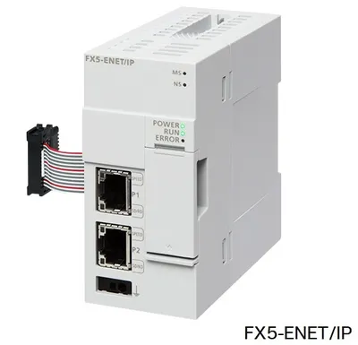 Available on requestFX5-ENET/IP Mitsubishi MELSEC iQ-F Series Network/communication module
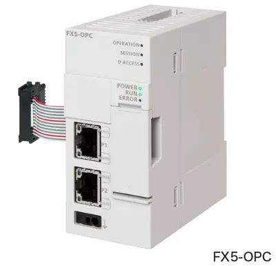 Available on requestFX5-OPC Mitsubishi MELSEC iQ-F Series Network/communication module
 Available on requestFX5-SDCD Mitsubishi MELSEC iQ-F Series Option
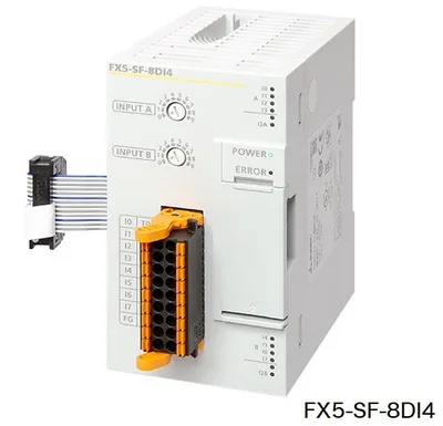 Available on requestFX5-SF-8DI4 Mitsubishi MELSEC iQ-F Series Safety Extension Module
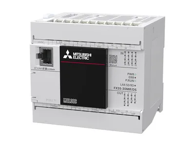 Available on requestFX5S-30MR/DS Mitsubishi MELSEC iQ-F Series CPU Module
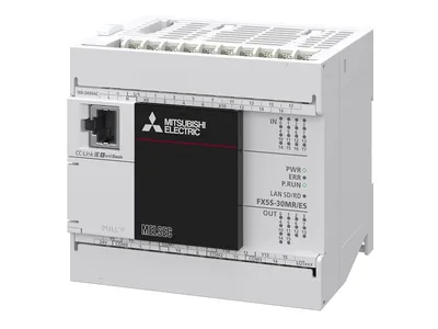 Available on requestFX5S-30MR/ES Mitsubishi MELSEC iQ-F Series CPU Module
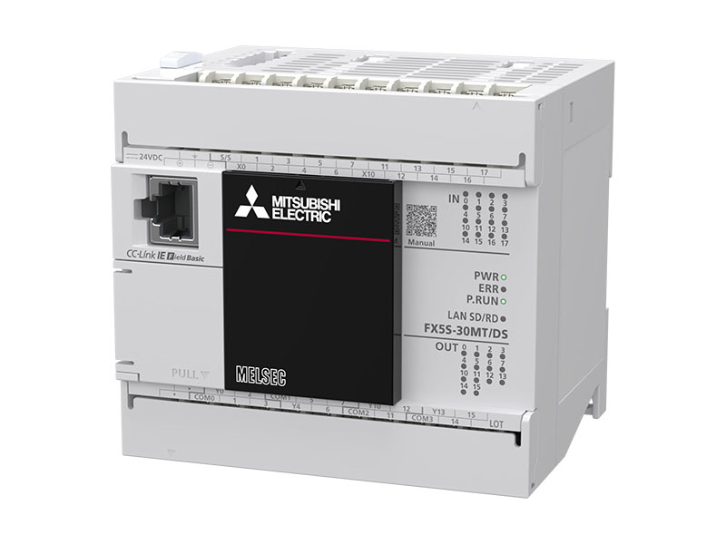 Available on requestFX5S-30MT/DS Mitsubishi MELSEC iQ-F Series CPU Module
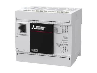 Available on requestFX5S-30MT/DSS Mitsubishi MELSEC iQ-F Series CPU Module