




.svg&w=240)



















B&R XEPcIMC200.02
I/O module, 43 digital inputs, 6 analog inputs
- MPN
- XEPcIMC200.02
Price and lead time confirmed within 1 business day
Request a Quote
- 12-month warranty (new) · 3-month (used/refurbished)
- 30-day returns, no restocking fee on unused parts
- Ships via



What is the B&R XEPcIMC200.02?
CPU I/O board, ARM Cortex-A9, 667 MHz, 2 GB flash memory, 512 MB DDR3L SDRAM, 64 kB FRAM, 24 VDC, 2x Ethernet interface, 1x CAN bus, 1x RS485 interface, 1x USB 2.0 interface, 1x POWERLINK interface, 1x X2X Link interface, 43 digital inputs, 24 VDC, sink/source, 2 event counters or gate time / period measurement, 33 digital outputs, 24 VDC, 2 A (50%), 20 digital outputs, 24 VDC, 0.5 A, 2 PWM outputs, 3 A, 8 thermocouple inputs J, K, S, N, 4 analog inputs for potentiometers, 0 to 10 V, 0 to 20 mA, 4.5 V, 14-bit, 2 analog inputs ±10 V, 14-bit, 7 analog outputs, ±10 V, 12-bit
Specifications
Short description
| I/O module | 43 digital inputs, 6 analog inputs, 53 digital outputs, 7 analog outputs, 8 thermocouples, 2 PWM outputs |
| Interfaces | 2x Ethernet, 1x CAN bus, 1x RS485 interface, 1x POWERLINK, 1x X2X Link, 1x USB |
General information
| System requirements – Automation Studio | 4.5.01 or later |
| System requirements – Automation Runtime | B4.53 or later |
| LEDs – Quantity | 10 |
| LEDs – Status | Supply voltage OK, operating state, module status, Ethernet, CAN, RS485, POWERLINK, X2X Link |
| Controller redundancy – Master capability | No |
| Support – ACOPOS support | No |
| Support – Visual Components support | No |
| Support – Safety support | No |
| Certifications – CE | Yes |
| B&R ID code | 0x2AD2 |
| Cooling | Passive |
| Power button | No |
| Reset button | Yes |
| Buzzer | No |
| Electrical isolation | Thermocouples, Ethernet 1 (IF2), Ethernet 2 (IF3), POWERLINK (IF9) and X2X (IF10) isolated from each other and from other interfaces; Power supply not isolated from channel, and channel not isolated from channel |
Controller
| Processor – Data code | 24 kB |
| Processor – Program code | 32 kB |
| Processor – Type | ARM Cortex-A9 |
| Processor – Clock frequency | 667 MHz |
| Processor – L2 cache | 256 kB |
| Standard memory – RAM | 512 MB DDR3 SDRAM |
| Application memory – Guaranteed | 40 TB |
| Application memory – Results for 5 years | 21.9 GB/day |
| Application memory – Type | 2 GB eMMC flash memory |
| Application memory – Data retention | 10 years |
| Application memory – Guaranteed erase/write cycles | 20,000 |
| Application memory – Error-correcting code (ECC) | Yes |
| Bootloader | Automation Runtime: A4.11 |
| CompactFlash slot | 0 |
| Real-time clock | Yes, 1 s resolution, >±10 ppm accuracy at 25°C (note: The real-time clock is backed up for approx. 1000 hours @ 25°C by a gold foil capacitor. The gold foil capacitor is completely charged after 3 continuous hours of operation.) |
| FPU | Yes |
| Mode/Node switches | No |
| Remanent variables | 64 kB FRAM, retention >10 years (note: The memory size for remanent variables is configurable in Automation Studio.) |
| Shortest task class cycle time | 1 ms |
| Typical instruction cycle time | 0.01 μs |
| Temperature cutoff | Yes |
Interfaces
| Interface IF2 – Physical layer | 10BASE-T/100BASE-TX |
| Interface IF2 – Half-duplex | Yes |
| Interface IF2 – Full-duplex | Yes |
| Interface IF2 – Autonegotiation | Yes |
| Interface IF2 – Auto-MDI/MDIX | Yes |
| Interface IF2 – Connection designation | X2 Ethernet1 |
| Interface IF2 – Type | Ethernet |
| Interface IF2 – Variant | 1x RJ45 shielded |
| Interface IF2 – Line length | Max. 100 m between 2 nodes (segment length) |
| Interface IF2 – Max. transfer rate | 10/100 Mbit/s |
| Interface IF3 – Physical layer | 10BASE-T/100BASE-TX |
| Interface IF3 – Half-duplex | Yes |
| Interface IF3 – Full-duplex | Yes |
| Interface IF3 – Autonegotiation | Yes |
| Interface IF3 – Auto-MDI/MDIX | Yes |
| Interface IF3 – Connection designation | X3 Ethernet2 |
| Interface IF3 – Type | Ethernet |
| Interface IF3 – Variant | 1x RJ45 shielded |
| Interface IF3 – Line length | Max. 100 m between 2 nodes (segment length) |
| Interface IF3 – Max. transfer rate | 10/100 Mbit/s |
| Interface IF4 – Connection designation | X1 USB1 |
| Interface IF4 – Type | USB 2.0 |
| Interface IF4 – Variant | Type A |
| Interface IF4 – Current-carrying capacity | 0.5 A |
| Interface IF6 – Connection designation | X4 CAN1 |
| Interface IF6 – Type | CAN bus |
| Interface IF6 – Variant | Connection via 0TB1110.9000 |
| Interface IF6 – Transfer rate | Max. 1 Mbit/s |
| Interface IF8 – Connection designation | X4 RS485 |
| Interface IF8 – Type | RS485 |
| Interface IF8 – Variant | Connection via 0TB1110.9000 |
| Interface IF8 – Transfer rate | Max. 115.2 kbit/s |
| Interface IF9 – Physical layer | 100BASE-TX |
| Interface IF9 – Half-duplex | Yes |
| Interface IF9 – Full-duplex | No |
| Interface IF9 – Autonegotiation | Yes |
| Interface IF9 – Auto-MDI/MDIX | Yes |
| Interface IF9 – Connection designation | X5 POWERLINK |
| Interface IF9 – Fieldbus | POWERLINK managing or controlled node |
| Interface IF9 – Type | Type 6Communication / POWERLINK / General information / Hardware - IF/LS" in Automation Help."> (note: For additional information, see section) |
| Interface IF9 – Variant | 1x RJ45 shielded |
| Interface IF9 – Line length | Max. 100 m between 2 nodes (segment length) |
| Interface IF9 – Transfer rate | Max. 100 Mbit/s |
| Interface IF10 – Connection designation | X6 X2X |
| Interface IF10 – Type | X2X Link |
| Interface IF10 – Number of stations | Max. 253 |
| Interface IF10 – Variant | 0TB1104.9000 |
| Interface IF10 – Internal bus power supply | No |
| Interface IF10 – Network topology | Line |
| Interface IF10 – Distance between 2 stations | Max. 100 m |
Digital inputs
| Switching threshold – Low | <5 V |
| Switching threshold – High | >15 V |
| Quantity | 41 inputs + 2 counter inputs |
| Nominal voltage | 24 VDC |
| Input voltage | 24 VDC ±20% |
| Input current at 24 VDC | 3.2 mA |
| Additional functions | Event counter, gate and period measurement |
| Circuit | Sink or source |
| Input delay | Counter inputs 1 to 2: <4 µs; Inputs 3 to 41: <1 ms |
Event counters
| Quantity | 2 |
| Signal form | Square wave pulse |
| Evaluation | Positive or negative edge, cyclic counter |
| Input frequency | Max. 100 kHz |
| Pulse length | >4 µs |
| Counter size | 16-bit |
| Supported inputs | Input 1: Counter 1; Input 2: Counter 2 |
Gate time measurement
| Counter frequency – Internal | 48 MHz, 12 MHz, 3 MHz, 750 kHz |
| Counter frequency – External | Max. 100 kHz (note: If channel 1 is configured for an external counter frequency, then input 2 is used for supplying the external counter frequency.) |
| Quantity | 2 |
| Signal form | Square wave pulse |
| Evaluation | Positive or negative edge |
| Counter size | 16-bit |
| Input frequency | Max. 100 kHz |
| Length of pause between pulses | 10 µs |
| Pulse length | 10 µs |
| Supported inputs | Input 1: Counter 1; Input 2: Counter 2 |
Period measurement
| Counter frequency – Internal | 48 MHz, 12 MHz, 3 MHz, 750 kHz |
| Counter frequency – External | Max. 100 kHz (note: If channel 1 is configured for an external counter frequency, then input 2 is used for supplying the external counter frequency.) |
| Quantity | 2 |
| Signal form | Square wave pulse |
| Supported inputs | Input 1: Counter 1; Input 2: Counter 2 |
| Input frequency | Max. 100 kHz |
| Evaluation | Positive or negative edge |
| Counter size | 16-bit |
Analog inputs
| Output format – Data type | INT |
| Output format – Voltage | Inputs 1 and 2: INT 0x8000 - 0x7FFF / 1 LSB = 0x0004 = 1.22 mV; Inputs 3 to 6: INT 0x0000 - 0x7FFF / 1 LSB = 0x0004 = 1.22 mV |
| Output format – Current | Inputs 3 to 6: INT 0x0000 - 0x7FFF / 1 LSB = 0x0008 = 4.88 µA |
| Max. error – Gain | 0.1% (note: Based on the current measured value. To avoid interference by switching DOs or PWM, it is recommended that the power supply (X4) be isolated from the DO/DI and PWM power supplies. With this isolated power supply, any analog sensors and actuators can/should also be operated.) |
| Max. error – Offset | 0.025% (note: Based on the measurement range. To avoid interference by switching DOs or PWM, it is recommended that the power supply (X4) be isolated from the DO/DI and PWM power supplies. With this isolated power supply, any analog sensors and actuators can/should also be operated.) |
| Max. error – Gain | 0.12% (note: Based on the current measured value. To avoid interference by switching DOs or PWM, it is recommended that the power supply (X4) be isolated from the DO/DI and PWM power supplies. With this isolated power supply, any analog sensors and actuators can/should also be operated.) |
| Max. error – Offset | 0.05% (note: Based on the measurement range. To avoid interference by switching DOs or PWM, it is recommended that the power supply (X4) be isolated from the DO/DI and PWM power supplies. With this isolated power supply, any analog sensors and actuators can/should also be operated.) |
| Max. gain drift – Voltage | 0.006%/°C (note: Based on the current measured value. To avoid interference by switching DOs or PWM, it is recommended that the power supply (X4) be isolated from the DO/DI and PWM power supplies. With this isolated power supply, any analog sensors and actuators can/should also be operated.) |
| Max. gain drift – Current | 0.009%/°C (note: Based on the current measured value. To avoid interference by switching DOs or PWM, it is recommended that the power supply (X4) be isolated from the DO/DI and PWM power supplies. With this isolated power supply, any analog sensors and actuators can/should also be operated.) |
| Max. offset drift – Voltage | 0.002%/°C (note: Based on the measurement range. To avoid interference by switching DOs or PWM, it is recommended that the power supply (X4) be isolated from the DO/DI and PWM power supplies. With this isolated power supply, any analog sensors and actuators can/should also be operated.) |
| Max. offset drift – Current | 0.004 %/°C (note: Based on the measurement range. To avoid interference by switching DOs or PWM, it is recommended that the power supply (X4) be isolated from the DO/DI and PWM power supplies. With this isolated power supply, any analog sensors and actuators can/should also be operated.) |
| Input filter – Cutoff frequency | Inputs 1 and 2: 1 kHz; Inputs 3 to 6: 10 kHz |
| Input filter – Slope | 60 dB |
| Input | Inputs 1 and 2: ±10 V; Inputs 3 to 6: 0 to 10 V, 0 to 20 mA or 0 to 100% (U pot ) |
| Input type | Inputs 1 and 2: Differential input; Inputs 3 to 6: Single-ended input |
| Digital converter resolution | 14-bit |
| Input impedance in signal range | 10 MΩ |
| Current channel load | <400 Ω |
| Input protection | Protection against wiring with supply voltage |
| Supply voltage U Pot for potentiometer | 4.5 V / Max. 50 mA |
| Measurement range | 0.5 to 10 kΩ |
Thermocouple temperature inputs
| Measurement range – FeCuNi: Type J | -210 to 1200°C |
| Measurement range – NiCrNi: Type K | -270 to 1372°C |
| Measurement range – NiCrSi: Type N | -270 to 1300°C |
| Measurement range – PtRhPt: Type S | -50 to 1768°C |
| Measurement range – Voltage | ±70 mV |
| Resolution – Sensor temperature | 0.1°C/LSB |
| Resolution – Voltage | 2.136 µV/LSB |
| Basic accuracy – Type J: Fe-CuNi | ±0.14% at 25°C (note: Based on the measurement range.) |
| Basic accuracy – Type K: NiCr-Ni | ±0.18% at 25°C (note: Based on the measurement range.) |
| Basic accuracy – Type N: NiCrSi-NiSi | ±0.16% at 25°C (note: Based on the measurement range.) |
| Basic accuracy – Type S: PtRh10-Pt | ±0.34% at 25°C (note: Based on the measurement range.) |
| Terminal temperature compensation – Internal | Yes |
| Terminal temperature compensation – Basic accuracy at 25°C not taking Pt1000 sensor into account | ±2°C after 10 minutes |
| Quantity | 8 |
| Digital converter resolution | 16-bit |
| Output format | INT |
Digital outputs
| Actuator power supply – Supply | External |
| Actuator power supply – Fuse | No internal fuse, the power supply of the outputs of each connector must be protected using a separate fuse of max. 15 A. |
| Quantity | 53 |
| Nominal output current | Screw clamp terminal blocks X12, X13 and X15:; Per output: 2 A; Per group: 2 A; Per screw clamp terminal block: 11 A; Screw clamp terminal blocks X14 and X16:; Per output: 0.5 A (note: Group: Two adjacent channels DOx and DOx+1, where x can be any odd number between 1 and 31.) |
| Output circuit | Sink |
| Output protection | Short-circuit and overload protection |
| Switching frequency (resistive load) | Max. 100 Hz |
| Switching delay | Max. 500 µs |
| Type | Low-side driver (Sink) |
| Supply voltage | Separately for each connector: 12 to 24 VDC ±20% |
PWM output
| Load – Resistive load | ≥8 Ω |
| Load – Inductive load | ≤10 mH |
| PWM pulse width – PWM mode | 15-bit + sign; ≥1 µs |
| PWM pulse width – Current mode | 15-bit + sign |
| Quantity | 2 |
| Type | Push/Pull |
| Supply voltage (permissible range) | External, 11 to 28 VDC |
| Nominal current | 3 A |
| Maximum load current | 3.5 A / output (note: Channel cut off if exceeded (overcurrent protection)) |
| PWM frequency | 15 Hz to 50 kHz |
| Output protection | Reverse polarity protection for supply voltage, must be protected externally |
| Configurable dither | Amplitude (8-bit), frequency (2 to 500 Hz) |
| Period duration resolution | 16-bit |
Analog outputs
| Max. error – Gain | 0.080%, based on the current output value |
| Max. error – Offset | 0.050%, based on the entire output range |
| Output format – Data type | INT |
| Output format – Voltage | INT 0x8000 - 0x7FFF / 1 LSB = 0x0010 = 4.88 mV |
| Range of values – 10 V | 0x7FFF |
| Range of values – 0 V | 0x0000 |
| Range of values – -10 V | 0x8000 |
| Quantity | 7 |
| Output | ±10 V |
| Digital converter resolution | 12-bit |
| Switch on/off behavior | Internal enable relay, for startup |
| Output protection | Protection against wiring with supply voltage, short-circuit proof |
| Max. load per output | ±10 mA (load ≥1 kΩ) |
| Max. gain drift | 0.08%, based on the current output value |
| Max. offset drift | 0.05%, based on the entire output range |
| Error caused by load change | 0.015% from 10 MΩ → 1 kΩ, resistive |
| Nonlinearity | 0.025%, based on the output range |
Power supply unit
| Voltage range | 24 VDC ±25% |
| Power consumption | 6.5 W |
| Voltage monitoring | Yes |
Operating conditions
| Mounting orientation – Horizontal | No |
| Mounting orientation – Vertical | Yes |
| Pollution degree per EN 60664-1 | 2 |
Ambient conditions
| Temperature – Operation | 0 to 50°C |
| Temperature – Storage | -40 to 85°C |
| Temperature – Transport | -40 to 85°C |
| Relative humidity – Operation | 10 to 90%, non-condensing |
| Relative humidity – Storage | 5 to 95%, non-condensing |
| Relative humidity – Transport | 5 to 95%, non-condensing |
Mechanical properties
| Dimensions – Width | 190 mm |
| Dimensions – Height | 198 mm |
| Dimensions – Depth | 31 mm |
| Module dimensions including mounting plates | 190 x 198 x 31 mm (W x H x D) |
Accessories
Required accessories (order separately)
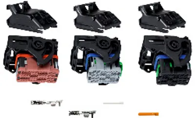
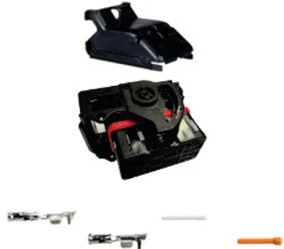
| XEPIMA419 | Miscellaneous — SMARTMOLD I/O connector set (112 I/Os) |
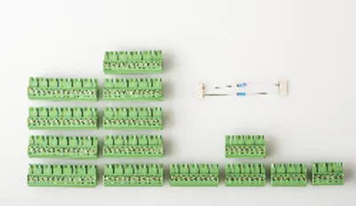
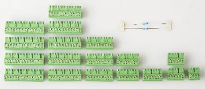
| XEPIMA200 | Miscellaneous — SMARTMOLD I/O connector set (119 I/Os) screw clamp terminal blocks |
| XEPIMA100 | Miscellaneous — SMARTMOLD I/O connector set (100 I/Os) screw clamp terminal blocks |
| X20TBS2 | Terminal blocks — Tool-free wiring thanks to push-in technology; Simple wire release using a lever This 4-pin terminal block is used to connect to various B&… |
| X20TBS1 | Terminal blocks — Tool-free wiring thanks to push-in technology; Simple wire release using a lever This 16-pin terminal block is used to connect to various B… |
Optional accessories (2)
| XEPIMA200.01 | Miscellaneous — SMARTMOLD I/O connector set (119 I/Os) cage clamp terminals |
| XEPIMA100.01 | Miscellaneous — SMARTMOLD I/O connector set (100 I/Os) cage clamp terminals |
Downloads & documentation
Official documents from B&R, downloaded directly from the manufacturer.
Data sheets & manuals
XEPcIMC200.02: frequently asked questions
When can XEPcIMC200.02 be shipped?
XEPcIMC200.02 is sourced on request — request a quote and we'll confirm the exact availability and shipping timeline for this specific unit.
Can I pick up XEPcIMC200.02 in person?
Local pickup from our Groningen, Netherlands warehouse may be possible — contact us before ordering to check availability and arrange a collection time.
Is express delivery available?
Yes — mention it when you request a quote for XEPcIMC200.02 and we'll include express shipping options in our reply.
My factory is down and I need this urgently — can you help?
For a critical breakdown, contact us directly at +31 (0)50-7110348 or sales@partnerplc.com — we can look into same-day courier or dedicated taxi/hotshot delivery for XEPcIMC200.02, subject to availability and destination.
More B&R parts

B&R XEPcIMC200.02Price and lead time confirmed within 1 business day
Request a Quote