




.svg&w=240)


















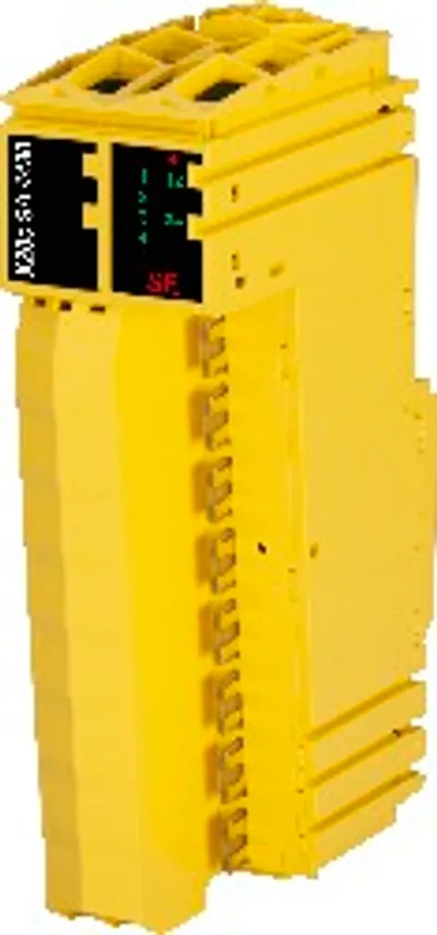
B&R X20cSC2432
I/O module, 2 safe type A digital inputs, 2 pulse outputs
- MPN
- X20cSC2432
- Category
- Digital mixed modules
Price and lead time confirmed within 1 business day
Request a Quote
- 12-month warranty (new) · 3-month (used/refurbished)
- 30-day returns, no restocking fee on unused parts
- Ships via



What is the B&R X20cSC2432?
2 safe digital inputs, sink circuit
2 pulse outputs
Software input filter configurable for each channel
2 safe relay outputs
Output type "Relay"
Relay module for 48 VAC / 24 VDC
Switching current 6 A
Normally open contact
Single-channel isolated outputs
The module is equipped with 2 safe digital inputs and 2 safe relay outputs. It is designed for a nominal voltage of 24 VDC.
The module can be used to read digital signals and for floating control of actuators in safety-related applications up to PL e or SIL 3.
The module is equipped with filters that are individually configurable for switch-on and switch-off behavior. The module also provides pulse signals for diagnosing the sensor line.
Safety relays are installed in the module. The positively driven feedback contacts are evaluated internally by the module. Safe digital output channels provide protection against automatic restart when network errors occur.
This module is designed for X20 12-pin terminal blocks.
Specifications
Short description
| I/O module | 2 safe type A digital inputs, 2 pulse outputs, 24 VDC, 2 relays with 1 normally open contact each, 48 VAC / 6 A, 24 VDC / 6 A |
General information
| Diagnostics – Module run/error | Yes, using LED status indicator and software |
| Diagnostics – Outputs | Yes, using LED status indicator and software |
| Diagnostics – Inputs | Yes, using LED status indicator and software |
| Blackout mode – Scope | Module |
| Blackout mode – Function | Module functionality |
| Blackout mode – Standalone mode | No |
| Power consumption – Bus | 0.26 W |
| Power consumption – Internal I/O | 1.15 W |
| Additional power dissipation caused by actuators (resistive) [W] – Relay outputsMechanical and electrical configuration" in the X20 system user's manual."> | 1.44 (note: Number of outputs x Contact resistance x Nominal output current 2 . For a calculation example, see section) |
| Additional power dissipation caused by actuators (resistive) [W] – Pulse outputsMechanical and electrical configuration" in the X20 system user's manual."> | 0.1 (note: Number of outputs x R DS(on) x Nominal output current 2 . This value also applies to sensors that are supplied via these outputs. For a calculation example, see section) |
| Electrical isolation – Channel - Bus | Yes |
| Electrical isolation – Channel - Channel | Yes |
| Certifications – EN 50155 | Yes |
| Certifications – EN 61810-3 | Yes |
| Certifications – CE | Yes |
| Certifications – UKCA | Yes |
| Certifications – CRA (Cyber Resilience Act) | In preparation |
| Certifications – Functional safety | cULus FSPC E361559; Energy and industrial systems; Certified for functional safety; ANSI UL 1998:2013 |
| Certifications – Functional safety | IEC 61508:2010, SIL 3; EN 62061:2005/A2:2015, SIL 3; EN ISO 13849-1:2015, Cat. 4 / PL e; IEC 61511:2004, SIL 3 |
| Certifications – Functional safety | EN 50156-1:2004 |
| Certifications – ATEX | Zone 2, II 3G Ex nA nC IIA T5 Gc; IP20, Ta (see X20 user's manual); FTZÚ 09 ATEX 0083X |
| Certifications – UL | cULus E115267; Industrial control equipment |
| Certifications – HazLoc | cCSAus 244665; Process control equipment; for hazardous locations; Class I, Division 2, Groups ABCD, T5 |
| Certifications – DNV | Temperature: A (0 to 45°C); Humidity: B (up to 100%); Vibration: A (0.7 g); EMC: B (bridge and open deck) |
| Certifications – LR | ENV1 |
| Certifications – KR | Yes |
| Certifications – ABS | Yes |
| Certifications – BV | EC21B ; Temperature: 5 - 45°C; Vibration: 0.7 g; EMC: Bridge and open deck |
| B&R ID code | 0xDD5D |
| Status indicators | I/O function per channel, operating state, module status |
Safety characteristics
| Note | See section "Safety characteristics". |
I/O power supply
| Nominal voltage | 24 VDC |
| Voltage range | 24 VDC -15% / +20% |
| Integrated protective function | Reverse polarity protection |
Safe digital inputs
| Input filter – Hardware | ≤150 μs |
| Input filter – Software | Configurable between 0 and 500 ms |
| Switching threshold – Low | <5 VDC |
| Switching threshold – High | >15 VDC |
| Quantity | 2 |
| Variant | Type A |
| Nominal voltage | 24 VDC |
| Input characteristics per EN 61131-2 | Type 1 |
| Input circuit | Sink |
| Input voltage | 24 VDC -15% / +20% |
| Input current at 24 VDC | Min. 2 mA to max. 4.59 mA (note: The input current specifications refer to the switched-on state of the input.) |
| Input resistance | Min. 5.23 kΩ |
| Error detection time | 100 ms |
| Insulation voltage between channel and bus | 500 V eff |
| Line length between signal source (pulse output or external signal) and input | Max. 60 m with unshielded line; Max. 400 m with shielded line |
Relay outputs
| Switching delay – 0 → 1 | <50 ms |
| Switching delay – 1 → 0 | <50 ms |
| Max. switching capacity – AC1 | 48 VAC / 6 A |
| Max. switching capacity – AC15 | 48 VAC / 3 A |
| Max. switching capacity – DC1 | 24 VDC / 6 A |
| Max. switching capacity – DC13 | 24 VDC / 5 A / 0.1 Hz |
| Max. switching capacity – UL 508 | B300 / R300 |
| Quantity | 2 |
| Variant | Relay / Normally open contact, internal high-side and low-side control |
| Nominal output current | 5 mA to 6 A |
| Diagnostic status | Contact position determined by positively driven contacts |
| Max. switching frequency | See section "Inrush current behavior for output channels". |
| Insulation voltage between channel and bus | Safe disconnection of 300 VAC per EN 50178 |
| Insulation voltage between channel and channel | 48 VAC |
| Contact resistance (without terminal block) | 20 mΩ |
| Contact service life | See "Contact service life". |
| Short-circuit/Overload protection | External 6 A gL/gG fuse (melting fuse), LS automat C characteristic 1.6 A |
| Switching voltage range | 5 to 24 VDC, 5 to 48 VAC |
| Coil voltage | 24 VDC -15% / +20% |
| Short-circuit proof | Yes, 1000 A (with specified short-circuit/overload protection) |
| Max. inrush current | 30 A for 20 ms |
| Overvoltage category per EN 60664-1 | II |
Pulse outputs
| Quantity | 2 |
| Variant | Push-Pull |
| Nominal output current | 50 mA |
| Output protection | Shutdown of individual channels in the event of overload or short circuit (note: The protective function is provided for max. 30 minutes for a continuous short circuit.) |
| Peak short-circuit current | 25 A for 5 ms |
| Short-circuit current | 1.4 A eff |
| Leakage current when the output is switched off | 0.1 mA |
| R DS(on) | 20 Ω |
| Switching voltage | I/O power supply minus voltage drop due to R DS(on) |
| Total nominal current | 100 mA |
Operating conditions
| Mounting orientation – Horizontal | Yes |
| Mounting orientation – Vertical | Yes |
| Installation elevation above sea level | 0 to 2000 m, no limitation |
| Degree of protection per EN 60529 | IP20 |
Ambient conditions
| Temperature – Horizontal mounting orientation | -25 to 60°C (note: Compared to the value in the X20 system user's manual, where the angle of the horizontal mounting orientation is specified as 70°, this only applies up to an angle of 85° for the X20(c)SC2432. Below this, the derating for face-up installation must be applied.) |
| Temperature – Vertical mounting orientation | -25 to 50°C |
| Temperature – Derating | See section "Derating". |
| Temperature – Starting temperature | Yes, -25°C |
| Temperature – Storage | -40 to 85°C |
| Temperature – Transport | -40 to 85°C |
| Relative humidity – Operation | Up to 100%, condensing |
| Relative humidity – Storage | 5 to 95%, non-condensing |
| Relative humidity – Transport | 5 to 95%, non-condensing |
Mechanical properties
| Note | Order 1x safety-keyed terminal block separately.; Order 1x safety-keyed bus module separately. |
| Pitch | 25 +0.2 mm |
Accessories
Required accessories (order separately)
| X20cBM33 | Bus modules — Bus module for SafeIO modules; The internal I/O power supply is continuous. The bus module is the base for all SafeIO modules. The internal… |
| X20TB52 | Terminal blocks — Tool-free wiring using push-in technology; Simple wire release using a lever; Labeling option for each terminal connection; Plain text labe… |
Downloads & documentation
Official documents from B&R, downloaded directly from the manufacturer.
Data sheets & manuals
CAD & dimension drawings
Certificates (16)
- 2226379 CSA Certificate of Compliance X20 X67
- 64331_A1 BV Certificate of Compliance X20
- ABS Certificate of Product Design Assessment - X20 IO Series
- E115267 UL Certificate of Compliance X20
- EU Data Act - X20-X67 SafeIO - Connected Product Information Notice
- EU Declaration FS PLC X20
- EU Declaration of Conformity CE_Declaration_FS_X20
- EU_Declaration_of_Conformity_X20_FuctionalSafety
- KR Type Approval Certificate MIL39390-AC003 (X20 System)
- Lloyds Register (X20 only)
- M6A 041745 0010 TÜV Süd FS Certificate SafeDESIGNER, SafeLOGIC, SafeIO
- M6A 041745 0013 TÜV Süd FS Certificate mapp Safety
- M6A 041745 0023 TÜV Süd FS Certificate Safety+
- RINA Type Approval Certificate - X20 / Power Panel T30
- TAA00000BJ DNV Type Approval Certificate X20
- UK Declaration FS PLC X20
X20cSC2432: frequently asked questions
When can X20cSC2432 be shipped?
X20cSC2432 is sourced on request — request a quote and we'll confirm the exact availability and shipping timeline for this specific unit.
Can I pick up X20cSC2432 in person?
Local pickup from our Groningen, Netherlands warehouse may be possible — contact us before ordering to check availability and arrange a collection time.
Is express delivery available?
Yes — mention it when you request a quote for X20cSC2432 and we'll include express shipping options in our reply.
My factory is down and I need this urgently — can you help?
For a critical breakdown, contact us directly at +31 (0)50-7110348 or sales@partnerplc.com — we can look into same-day courier or dedicated taxi/hotshot delivery for X20cSC2432, subject to availability and destination.
More B&R parts
B&R X20cSC2432Price and lead time confirmed within 1 business day
Request a Quote