






















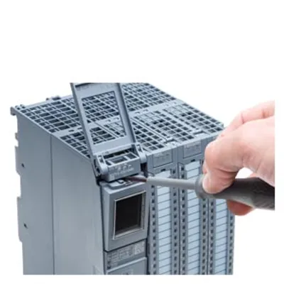
Siemens 6ES7615-7DF10-0AB0
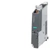
SIMATIC S7-1500, Drive Controller CPU 1507D TF with SINAMICS S120 Integrated; interfaces: 12 DI, 16 DI/DQ
- MPN
- 6ES7615-7DF10-0AB0
- Category
- CPU 1507D TF
Price and lead time confirmed within 1 business day
Request a Quote
- 12-month warranty (new) · 3-month (used/refurbished)
- 30-day returns, no restocking fee on unused parts
- Ships via



- 100% positive eBay feedback
What is the Siemens 6ES7615-7DF10-0AB0?
SIMATIC S7-1500, Drive Controller CPU 1507D TF with SINAMICS S120 Integrated; interfaces: 12 DI, 16 DI/DQ, 4 DRIVE-CLiQ, 3 PROFINET: 3+1+1 ports, 1 PROFIBUS, SIMATIC Memory Card required; supported firmware version: SIMATIC S7-1500 FW up to V3.1 (technology version up to V8.0), SINAMICS FW V5.2/V5.2 SP3
Specifications
General information
| Product type designation | CPU 1507D TF |
| HW functional status | FS13 |
| Firmware version | PLC: V3.1 / SINAMICS Integrated: V5.2 SP3 |
| Firmware version — FW update possible | Yes; PLC up to V3.1 / SINAMICS Integrated up to V5.2 SP3 |
| based on | SIMATIC S7-1500 TF-CPU and SINAMICS S120 |
| Product function — I&M data | Yes; I&M0 to I&M3 |
| Product function — Isochronous mode | Yes; with minimum OB 6x cycle of 250 µs |
| Product function — SysLog | Yes |
| Engineering with — STEP 7 TIA Portal configurable/integrated from version | V21 (FW V3.1) / V16 (FW V2.8) or higher |
| Integrated drive control — Number of axes for servo control, max. | 6 |
| Integrated drive control — Number of axes for vector control, max. | 6 |
| Integrated drive control — Number of axes for V/f control, max. | 12 |
| Integrated drive control — Remark | alternative control modes; drive control based on SINAMICS S120 CU320-2 (firmware version V5.x); functional subset compared to CU320-2: no free function blocks, ... ; for details, see the manual |
Configuration control
| via dataset | Yes |
Control elements
| Number of keys | 1; FUNCT button |
| Mode selector switch | 1 |
Supply voltage
| Rated value (DC) | 24 V |
| permissible range, lower limit (DC) | 20.4 V |
| permissible range, upper limit (DC) | 28.8 V |
| Reverse polarity protection | Yes |
| Mains buffering — Mains/voltage failure stored energy time | 3 ms; Refers to the power supply on the CPU section |
| Mains buffering — Repeat rate, min. | 1 event every 10 s |
Input current
| Current consumption (rated value) | 0.65 A; Without load on inputs/outputs, without supply via DRIVE- CLiQ/USB interface |
| Current consumption, max. | 13.1 A; With load |
| Inrush current, max. | 6 A; Rated value |
| I²t | 0.62 A²·s |
Power loss
| Power loss, typ. | 17 W |
Storage
| Number of slots for SIMATIC memory card | 1 |
| SIMATIC memory card required | Yes |
| Work memory — integrated (for program) | 15 Mbyte |
| Work memory — integrated (for data) | 40 Mbyte |
| Load memory — Plug-in (SIMATIC Memory Card), required | 12 Mbyte; Recommended at least when integrated drive is used |
| Load memory — Plug-in (SIMATIC Memory Card), max. | 32 Gbyte |
| Backup — maintenance-free | Yes |
CPU-blocks
| Number of elements (total) | 20 000; Blocks (OB, FB, FC, DB) and UDTs |
| DB — Number range | 1 ... 60 999; subdivided into: number range that can be used by the user: 1 ... 59 999, and number range of DBs created via SFC 86: 60 000 ... 60 999 |
| DB — Size, max. | 16 Mbyte; For DBs with absolute addressing, the max. size is 64 KB |
| FB — Number range | 0 ... 65 535 |
| FB — Size, max. | 1 Mbyte |
| FC — Number range | 0 ... 65 535 |
| FC — Size, max. | 1 Mbyte |
| OB — Size, max. | 1 Mbyte |
| OB — Number of free cycle OBs | 100 |
| OB — Number of time alarm OBs | 20 |
| OB — Number of delay alarm OBs | 20 |
| OB — Number of cyclic interrupt OBs | 20; with minimum OB 3x cycle of 100 µs |
| OB — Number of process alarm OBs | 50 |
| OB — Number of DPV1 alarm OBs | 3 |
| OB — Number of isochronous mode OBs | 3 |
| OB — Number of technology synchronous alarm OBs | 2 |
| OB — Number of startup OBs | 100 |
| OB — Number of asynchronous error OBs | 4 |
| OB — Number of synchronous error OBs | 2 |
| OB — Number of diagnostic alarm OBs | 1 |
| Nesting depth — per priority class | 24; Up to 8 possible for F-blocks |
Counters, timers and their retentivity
| S7 counter — Number | 2 048 |
| S7 counter — Retentivity — can be set | Yes |
| IEC counter — Number | Any (only limited by the main memory) |
| IEC counter — Retentivity — adjustable | Yes |
| S7 timer — Number | 2 048 |
| S7 timer — Retentivity — adjustable | Yes |
| IEC timer — Number | Any (only limited by the main memory) |
| IEC timer — Retentivity — can be set | Yes |
Data areas and their retentivity
| Retentive data area (incl. timers, counters, flags), max. | 700 kbyte; in total; for bit memories, timers, counters, DBs, and technology data (axes) |
| Flag — Size, max. | 16 kbyte |
| Flag — Number of clock memories | 8; 8 clock memory bit, grouped into one clock memory byte |
| Data blocks — Retentivity adjustable | Yes |
| Data blocks — Retentivity preset | No |
| Local data — per priority class, max. | 64 kbyte; max. 16 KB per block |
Address area
| Number of IO modules | 16 384; max. number of modules / submodules |
| I/O address area — Inputs | 32 kbyte; All inputs are in the process image |
| I/O address area — Outputs | 32 kbyte; All outputs are in the process image |
| I/O address area — per integrated IO subsystem — Inputs (volume) | 32 kbyte; Max. 32 KB via X150; max. 8 KB via X160 or X126 |
| I/O address area — per integrated IO subsystem — Outputs (volume) | 32 kbyte; Max. 32 KB via X150; max. 8 KB via X160 or X126 |
| Subprocess images — Number of subprocess images, max. | 32 |
Hardware configuration
| Number of distributed IO systems | 64; A distributed I/O system is characterized not only by the integration of distributed I/O via PROFINET or PROFIBUS, but also by the connection of I/O via AS-i master modules or links (e.g. IE/PB-Link) |
| Number of DP masters — integrated | 1 |
| Number of DP masters — Via CM | Expansion via CMs / CPs (PROFIBUS, PROFINET, Ethernet) not possible; these CMs / CPs can only be operated in a central rack |
| Number of IO Controllers — Integrated | 2 |
| Number of IO Controllers — via CM | Expansion via CMs / CPs (PROFIBUS, PROFINET, Ethernet) not possible; these CMs / CPs can only be operated in a central rack |
| PtP CM — Number of PtP CMs | The number of connectable PtP CMs (distributed) is only limited by the number of available slots |
Time of day
| Clock — Type | Hardware clock |
| Clock — Backup time | 6 wk; At 40 °C ambient temperature, typically |
| Clock — Deviation per day, max. | 10 s; Typ.: 2.4 s |
| Operating hours counter — Number | 16 |
| Clock synchronization — supported | Yes |
| Clock synchronization — to DP, master | Yes |
| Clock synchronization — on DP, device | Yes |
| Clock synchronization — in AS, master | Yes |
| Clock synchronization — in AS, device | Yes |
| Clock synchronization — on Ethernet via NTP | Yes |
Digital inputs
| integrated channels (DI) | 28; max. depending on parameterization |
| Digital inputs, parameterizable | Yes; 12 DI, 8 DI/DQ (X122/X132, SINAMICS Integrated) + 8 DI/DQ (X142, PLC) |
| Sourcing/sinking input | P-reading |
| Input characteristic curve in accordance with IEC 61131, type 3 | Yes |
| Digital input functions, parameterizable — Freely usable digital input | Yes; Max. 20 (X122/X132) + max. 8 (X142) |
| Digital input functions, parameterizable — Probe | Yes; Max. 8 (X122/X132) + max. 8 (X142) |
| Digital input functions, parameterizable — Digital input with time stamp | Yes; Max. 8 (X142); e.g. for probes |
| Digital input functions, parameterizable — Counter | Yes; Max. 8 (X142); event/cycle duration measurement |
| Digital input functions, parameterizable — Digital input with oversampling | Yes; Max. 8 (X142); 32-fold oversampling |
| Input voltage — Type of input voltage | DC |
| Input voltage — Rated value (DC) | 24 V |
| Input voltage — for signal "0" | -3 to +5V |
| Input voltage — for signal "1" | +11 to +30V |
| Input voltage — permissible voltage at input, min. | -3 V |
| Input voltage — permissible voltage at input, max. | 30 V |
| Input current — for signal "1", typ. | 4 mA |
| Input delay (for rated value of input voltage) — Minimum pulse width for program reactions | 5 µs; for X122/X132/X142 (DI/DQ as DI; for X142 with filter setting 1 µs) |
| Input delay (for rated value of input voltage) — for standard inputs — parameterizable | No; For X122/X132 |
| Input delay (for rated value of input voltage) — for standard inputs — with "0" to "1", typ. | For X122/X132: 10 µs (DI) / 5 µs (DI/DQ as DI) |
| Input delay (for rated value of input voltage) — for standard inputs — with "1" to "0", typ. | For X122/X132: 30 µs (DI) / 5 µs (DI/DQ as DI) |
| Input delay (for rated value of input voltage) — for interrupt inputs — Parameterizable | Yes; identical to those for technological functions |
| Input delay (for rated value of input voltage) — for technological functions — Parameterizable | Yes; For X142, additionally adjustable input filter: 1 µs / 125 µs |
| Input delay (for rated value of input voltage) — for technological functions — with "0" to "1", typ. | 5 µs; For X142; HW delay |
| Input delay (for rated value of input voltage) — for technological functions — with "1" to "0", typ. | 5 µs; For X142; HW delay |
| Cable length — shielded, max. | 30 m; For technological functions: Shielding of the DI recommended depending on the requirements |
| Cable length — unshielded, max. | 30 m |
Digital outputs
| Type of digital output | Transistor |
| integrated channels (DO) | 16; max. depending on parameterization |
| Current-sinking | Yes; With High Speed output |
| Current-sourcing | Yes; Optionally as a P-switch or high-speed push-pull switch (high-speed output) |
| Digital outputs, parameterizable | Yes; 8 DI/DQ (X122/X132, SINAMICS Integrated) + 8 DI/DQ (X142, PLC) |
| Short-circuit protection | Yes; electronic/thermal |
| Short-circuit protection — Response threshold, typ. | X122/X132: 1.4 A / X142: 0.9 A (high-speed output: 0.7 A) |
| Limitation of inductive shutdown voltage to | X122/X132: max. -60 V / X142: max. -64.5 V |
| Controlling a digital input | Yes |
| minimum pulse duration | 2 µs; For high-speed output, single pulse |
| Digital output functions, parameterizable — Freely usable digital output | Yes; Max. 8 (X122/X132) + max. 8 (X142) |
| Digital output functions, parameterizable — Digital output with time stamp | Yes; Max. 8 (X142); e.g. for output cams |
| Digital output functions, parameterizable — PWM output | Yes; Max. 8 (X142) |
| Digital output functions, parameterizable — PWM output — Cycle duration, parameterizable | Yes; Base frequency 1 / 2 / 4 / 8 / 16 kHz; specification of interpulse period ratio over 32-bit pattern |
| Digital output functions, parameterizable — PWM output — ON period, min. | 0 % |
| Digital output functions, parameterizable — PWM output — ON period, max. | 100 % |
| Digital output functions, parameterizable — PWM output — Resolution of the duty cycle | 3.125 % |
| Digital output functions, parameterizable — Digital output with oversampling | Yes; Max. 8 (X142) |
| Switching capacity of the outputs — with resistive load, max. | 0.5 A; 0.4 A for high-speed output |
| Switching capacity of the outputs — on lamp load, max. | 5 W |
| Load resistance range — lower limit | 48 Ω; with 24 V DC supply |
| Output voltage — Type of output voltage | DC |
| Output voltage — Rated value (DC) | 24 V |
| Output voltage — for signal "0", max. | 28.8 V |
| Output voltage — for signal "1", min. | 20.4 V |
| Output current — for signal "1" rated value | 0.5 A; 0.4 A for high-speed output |
| Output current — for signal "1" permissible range, min. | 2 mA |
| Output current — for signal "1" permissible range, max. | 0.6 A; 0.44 A for high-speed output |
| Output delay with resistive load — "0" to "1", typ. | 100 µs; For X122/X132; at 48 ohm load |
| Output delay with resistive load — "1" to "0", typ. | 150 µs; For X122/X132; at 48 ohm load |
| Output delay with resistive load — for technological functions — "0" to "1", typ. | 1 µs; For X142 |
| Output delay with resistive load — for technological functions — "1" to "0", typ. | 1 µs; For X142 as a high-speed output; 150 µs for standard output |
| Parallel switching of two outputs — for logic links | Yes; For technological functions and high-speed outputs: No |
| Parallel switching of two outputs — for uprating | No |
| Parallel switching of two outputs — for redundant control of a load | Yes; For technological functions and high-speed outputs: No |
| Switching frequency — with resistive load, max. | 35 kHz; With High Speed output, 1 kHz with standard output |
| Switching frequency — with inductive load, max. | 2 Hz; Max. 1 J per channel |
| Switching frequency — on lamp load, max. | 11 Hz |
| Total current of the outputs — Current per module, max. | 8 A |
| Cable length — shielded, max. | 30 m |
| Cable length — unshielded, max. | 30 m |
Interfaces
| Number of PROFINET interfaces | 3 |
| Number of PROFIBUS interfaces | 1 |
| Number of USB interfaces | 2; USB 3.0 (without function, no connection permissible) |
| Number of DRIVE-CLiQ interfaces | 4; DRIVE-CLiQ interfaces (24 V / 450 mA per interface for connecting encoders/measuring systems) |
1. Interface
| Interface types — RJ 45 (Ethernet) | Yes; X150 |
| Interface types — Number of ports | 3 |
| Interface types — integrated switch | Yes |
| Protocols — IP protocol | Yes; IPv4 |
| Protocols — PROFINET IO Controller | Yes |
| Protocols — PROFINET IO device | Yes |
| Protocols — SIMATIC communication | Yes |
| Protocols — Open IE communication | Yes; Optionally also encrypted |
| Protocols — Web server | Yes |
| Protocols — Media redundancy | Yes |
| PROFINET IO Controller — Services — Isochronous mode | Yes |
| PROFINET IO Controller — Services — Direct data exchange | Yes; Requirement: IRT and isochronous mode (MRPD optional) |
| PROFINET IO Controller — Services — IRT | Yes |
| PROFINET IO Controller — Services — Dynamic Frame Packing (DFP) | Yes |
| PROFINET IO Controller — Services — PROFIenergy | Yes; per user program |
| PROFINET IO Controller — Services — Prioritized startup | Yes; Max. 32 PROFINET devices |
| PROFINET IO Controller — Services — Number of connectable IO Devices, max. | 256; In total, up to 1 000 distributed I/O devices can be connected via AS-i, PROFIBUS or PROFINET |
| PROFINET IO Controller — Services — Of which IO devices with IRT, max. | 64 |
| PROFINET IO Controller — Services — Number of connectable IO Devices for RT, max. | 256 |
| PROFINET IO Controller — Services — of which in line, max. | 256 |
| PROFINET IO Controller — Services — Number of IO Devices that can be simultaneously activated/deactivated, max. | 8; in total across all interfaces |
| PROFINET IO Controller — Services — Number of IO Devices per tool, max. | 8 |
| PROFINET IO Controller — Services — Updating times | The minimum value of the update time also depends on communication share set for PROFINET IO, on the number of IO devices, and on the quantity of configured user data |
| PROFINET IO Controller — Services — PROFINET Security Class | 1 |
| PROFINET IO Controller — Update time for IRT — for send cycle of 250 µs | 250 µs to 4 ms |
| PROFINET IO Controller — Update time for IRT — for send cycle of 500 µs | 500 µs to 8 ms |
| PROFINET IO Controller — Update time for IRT — for send cycle of 1 ms | 1 ms to 16 ms |
| PROFINET IO Controller — Update time for IRT — for send cycle of 2 ms | 2 ms to 32 ms |
| PROFINET IO Controller — Update time for IRT — for send cycle of 4 ms | 4 ms to 64 ms |
| PROFINET IO Controller — Update time for IRT — With IRT and parameterization of "odd" send cycles | Update time = set "odd" send clock (any multiple of 125 µs: 375 µs, 625 µs ... 3 875 µs) |
| PROFINET IO Controller — Update time for RT — for send cycle of 250 µs | 250 µs to 128 ms |
| PROFINET IO Controller — Update time for RT — for send cycle of 500 µs | 500 µs to 256 ms |
| PROFINET IO Controller — Update time for RT — for send cycle of 1 ms | 1 ms to 512 ms |
| PROFINET IO Controller — Update time for RT — for send cycle of 2 ms | 2 ms to 512 ms |
| PROFINET IO Controller — Update time for RT — for send cycle of 4 ms | 4 ms to 512 ms |
| PROFINET IO Device — Services — Isochronous mode | No |
| PROFINET IO Device — Services — IRT | Yes |
| PROFINET IO Device — Services — Dynamic Frame Packing (DFP) | No |
| PROFINET IO Device — Services — PROFIenergy | Yes; per user program |
| PROFINET IO Device — Services — Prioritized startup | Yes |
| PROFINET IO Device — Services — Shared device | Yes |
| PROFINET IO Device — Services — Number of IO Controllers with shared device, max. | 4 |
| PROFINET IO Device — Services — activation/deactivation of I-devices | Yes; per user program |
| PROFINET IO Device — Services — Asset management record | Yes; per user program |
| PROFINET IO Device — Services — PROFINET Security Class | SNMP Configuration and DCP Read Only |
2. Interface
| Interface types — RJ 45 (Ethernet) | Yes; X160 |
| Interface types — Number of ports | 1 |
| Interface types — integrated switch | No |
| Protocols — IP protocol | Yes; IPv4 |
| Protocols — PROFINET IO Controller | Yes |
| Protocols — PROFINET IO Device | Yes |
| Protocols — SIMATIC communication | Yes |
| Protocols — Open IE communication | Yes; Optionally also encrypted |
| Protocols — Web server | Yes |
| Protocols — Media redundancy | No |
| PROFINET IO Controller — Services — Isochronous mode | No |
| PROFINET IO Controller — Services — Direct data exchange | No |
| PROFINET IO Controller — Services — IRT | No |
| PROFINET IO Controller — Services — PROFIenergy | Yes; per user program |
| PROFINET IO Controller — Services — Prioritized startup | No |
| PROFINET IO Controller — Services — Number of connectable IO Devices, max. | 128; In total, up to 1 000 distributed I/O devices can be connected via AS-i, PROFIBUS or PROFINET |
| PROFINET IO Controller — Services — Number of connectable IO Devices for RT, max. | 128 |
| PROFINET IO Controller — Services — of which in line, max. | 128 |
| PROFINET IO Controller — Services — Number of IO Devices that can be simultaneously activated/deactivated, max. | 8; in total across all interfaces |
| PROFINET IO Controller — Services — IO Devices changing during operation (partner ports), supported | Yes |
| PROFINET IO Controller — Services — Number of IO Devices per tool, max. | 8 |
| PROFINET IO Controller — Services — Updating times | The minimum value of the update time also depends on communication share set for PROFINET IO, on the number of IO devices, and on the quantity of configured user data |
| PROFINET IO Controller — Services — PROFINET Security Class | 1 |
| PROFINET IO Controller — Update time for RT — for send cycle of 1 ms | 1 ms to 512 ms |
| PROFINET IO Device — Services — Isochronous mode | No |
| PROFINET IO Device — Services — IRT | No |
| PROFINET IO Device — Services — PROFIenergy | Yes; per user program |
| PROFINET IO Device — Services — Prioritized startup | No |
| PROFINET IO Device — Services — Shared device | Yes |
| PROFINET IO Device — Services — Number of IO Controllers with shared device, max. | 4 |
| PROFINET IO Device — Services — activation/deactivation of I-devices | Yes; per user program |
| PROFINET IO Device — Services — Asset management record | Yes; per user program |
| PROFINET IO Device — Services — PROFINET Security Class | SNMP Configuration and DCP Read Only |
3. Interface
| Interface types — RJ 45 (Ethernet) | Yes; X130 |
| Interface types — Number of ports | 1 |
| Interface types — integrated switch | No |
| Protocols — IP protocol | Yes; IPv4 |
| Protocols — PROFINET IO Controller | No |
| Protocols — PROFINET IO device | No |
| Protocols — SIMATIC communication | Yes |
| Protocols — Open IE communication | Yes; Optionally also encrypted |
| Protocols — Web server | Yes |
4. Interface
| Interface types — RS 485 | Yes; X126 |
| Interface types — Number of ports | 1 |
| Protocols — PROFIBUS DP master | Yes |
| Protocols — PROFIBUS DP device | No |
| Protocols — SIMATIC communication | Yes |
| PROFIBUS DP master — Number of connections, max. | 48; for the integrated PROFIBUS DP interface |
| PROFIBUS DP master — max. number of DP devices | 125; In total, up to 1 000 distributed I/O devices can be connected via AS-i, PROFIBUS or PROFINET |
| PROFIBUS DP master — Services — Equidistance | Yes |
| PROFIBUS DP master — Services — Isochronous mode | Yes |
| PROFIBUS DP master — Services — activation/deactivation of DP devices | Yes |
Interface types
| RJ 45 (Ethernet) — 100 Mbps | Yes |
| RJ 45 (Ethernet) — 1000 Mbps | Yes; Only at the X130 interface |
| RJ 45 (Ethernet) — Autonegotiation | Yes |
| RJ 45 (Ethernet) — Autocrossing | Yes |
| RJ 45 (Ethernet) — Industrial Ethernet status LED | Yes; LINK and ACTIVITY |
| RS 485 — Transmission rate, max. | 12 Mbit/s |
Protocols
| PROFIsafe | Yes; V2.4 / V2.6 (V2.6 only with PROFINET) |
| Number of connections — Number of connections, max. | 384; Via integrated interfaces of the CPU |
| Number of connections — Number of connections reserved for ES/HMI/web | 10 |
| Number of connections — Number of connections via integrated interfaces | 320 |
| Number of connections — Number of S7 routing paths | 64; in total, only 16 S7-Routing connections are supported via PROFIBUS |
| Redundancy mode — PROFINET system redundancy (S2) | No |
| Redundancy mode — PROFINET system redundancy (R1) | No |
| Redundancy mode — H-Sync forwarding | Yes |
| Redundancy mode — Media redundancy — Media redundancy | only via interface X150 |
| Redundancy mode — Media redundancy — MRP | Yes; MRP Automanager according to IEC 62439-2 Edition 2.0, MRP Manager; MRP Client |
| Redundancy mode — Media redundancy — MRP interconnection, supported | Yes; as MRP ring node according to IEC 62439-2 Edition 3.0 |
| Redundancy mode — Media redundancy — MRPD | Yes; Requirement: IRT |
| Redundancy mode — Media redundancy — Switchover time on line break, typ. | 200 ms; For MRP, bumpless for MRPD |
| Redundancy mode — Media redundancy — Number of stations in the ring, max. | 50 |
| SIMATIC communication — PG/OP communication | Yes; encryption with TLS V1.3 pre-selected |
| SIMATIC communication — S7 routing | Yes |
| SIMATIC communication — Data record routing | Yes |
| SIMATIC communication — S7 communication, as server | Yes |
| SIMATIC communication — S7 communication, as client | Yes |
| SIMATIC communication — User data per job, max. | See online help (S7 communication, user data size) |
| Open IE communication — TCP/IP | Yes |
| Open IE communication — TCP/IP — Data length, max. | 64 kbyte |
| Open IE communication — TCP/IP — several passive connections per port, supported | Yes |
| Open IE communication — ISO-on-TCP (RFC1006) | Yes |
| Open IE communication — ISO-on-TCP (RFC1006) — Data length, max. | 64 kbyte |
| Open IE communication — UDP | Yes |
| Open IE communication — UDP — Data length, max. | 2 kbyte; 1 472 bytes for UDP broadcast |
| Open IE communication — UDP — UDP multicast | Yes; 128 multicast circuits (of which max. 5 via X150) |
| Open IE communication — DHCP | Yes |
| Open IE communication — DNS | Yes |
| Open IE communication — SNMP | Yes |
| Open IE communication — DCP | Yes |
| Open IE communication — LLDP | Yes |
| Open IE communication — Encryption | Yes; Optional |
| Web server — HTTP | Yes; Standard and user pages |
| Web server — HTTPS | Yes; Standard and user pages |
| Web server — web API — Number of sessions, max. | 200 |
| Web server — web API — number of simultaneous HTTP calls, max. | 4 |
| Web server — web API — HTTP request body, max. | 131 072 byte |
| OPC UA — Runtime license required | Yes; "Large" license required |
| OPC UA — OPC UA Client | Yes; Data Access (registered Read/Write), Method Call |
| OPC UA — OPC UA Client — Application authentication | Yes |
| OPC UA — OPC UA Client — Security policies | Available security policies: None, Basic128Rsa15, Basic256Rsa15, Basic256Sha256 |
| OPC UA — OPC UA Client — User authentication | "anonymous" or by user name & password |
| OPC UA — OPC UA Client — Number of connections, max. | 40 |
| OPC UA — OPC UA Client — Number of nodes of the client interfaces, recommended max. | 5 000 |
| OPC UA — OPC UA Client — Number of elements for one call of OPC_UA_NodeGetHandleList/OPC_UA_ReadList/OPC_UA_WriteList, max. | 300 |
| OPC UA — OPC UA Client — Number of elements for one call of OPC_UA_NameSpaceGetIndexList, max. | 20 |
| OPC UA — OPC UA Client — Number of elements for one call of OPC_UA_MethodGetHandleList, max. | 100 |
| OPC UA — OPC UA Client — Number of simultaneous calls of the client instructions for session management, per connection, max. | 1 |
| OPC UA — OPC UA Client — Number of simultaneous calls of the client instructions for data access, per connection, max. | 5 |
| OPC UA — OPC UA Client — Number of registerable nodes, max. | 5 000 |
| OPC UA — OPC UA Client — Number of registerable method calls of OPC_UA_MethodCall, max. | 100 |
| OPC UA — OPC UA Client — Number of inputs/outputs when calling OPC_UA_MethodCall, max. | 20 |
| OPC UA — OPC UA Server | Yes; Data Access (Read, Write, Subscribe), Method Call, Alarms & Condition (A&C), Custom Address Space |
| OPC UA — OPC UA Server — Application authentication | Yes |
| OPC UA — OPC UA Server — Security policies | available security policies: None, Basic128Rsa15, Basic256Rsa15, Basic256Sha256, Aes128Sha256RsaOaep, Aes256Sha256RsaPss |
| OPC UA — OPC UA Server — User authentication | "anonymous" or by user name & password |
| OPC UA — OPC UA Server — GDS support (certificate management) | Yes |
| OPC UA — OPC UA Server — Number of sessions, max. | 64 |
| OPC UA — OPC UA Server — Number of accessible variables, max. | 200 000 |
| OPC UA — OPC UA Server — Number of registerable nodes, max. | 50 000 |
| OPC UA — OPC UA Server — Number of subscriptions per session, max. | 50 |
| OPC UA — OPC UA Server — Sampling interval, min. | 10 ms |
| OPC UA — OPC UA Server — Publishing interval, min. | 10 ms |
| OPC UA — OPC UA Server — Number of server methods, max. | 100 |
| OPC UA — OPC UA Server — Number of inputs/outputs per server method, max. | 20 |
| OPC UA — OPC UA Server — Number of monitored items, recommended max. | 10 000; for 1 s sampling interval and 1 s send interval |
| OPC UA — OPC UA Server — Number of server interfaces, max. | 10 of each "Server interfaces" / "Companion specification" type and 20 of the type "Reference namespace" |
| OPC UA — OPC UA Server — Number of nodes for user-defined server interfaces, max. | 50 000 |
| OPC UA — Alarms and Conditions | Yes |
| OPC UA — Alarms and Conditions — Number of program alarms | 400 |
| OPC UA — Alarms and Conditions — Number of alarms for system diagnostics | 200 |
| Further protocols — MODBUS | Yes; MODBUS TCP |
Isochronous mode
| Equidistance | Yes |
| Jitter, max. | 1 µs |
S7 message functions
| Number of login stations for message functions, max. | 64 |
| number of subscriptions, max. | 750 |
| number of tags/attributes for subscriptions, max. | 50 000 |
| Program alarms | Yes |
| Number of configurable program messages, max. | 10 000; Program messages are generated by the "Program_Alarm" block, ProDiag or GRAPH |
| Number of loadable program messages in RUN, max. | 10 000 |
| Number of simultaneously active program alarms — Number of program alarms | 4 000 |
| Number of simultaneously active program alarms — Number of alarms for system diagnostics | 1 000 |
| Number of simultaneously active program alarms — Number of alarms for motion technology objects | 480 |
Test commissioning functions
| Joint commission (Team Engineering) | Yes; Parallel online access possible for up to 10 engineering systems |
| Status block | Yes; Up to 16 simultaneously (in total across all ES clients) |
| Single step | No |
| Number of breakpoints | 20 |
| Profiling | No |
| Status/control — Status/control variable | Yes; without fail-safe |
| Status/control — Variables | inputs/outputs, bit memories, DBs, peripheral I/Os (without fail-safe), times, counters |
| Status/control — Number of variables, max. — of which status variables, max. | 200; per job |
| Status/control — Number of variables, max. — of which control variables, max. | 200; per job |
| Forcing — Forcing | Yes; without fail-safe |
| Forcing — Forcing, variables | peripheral inputs/outputs (without fail-safe) |
| Forcing — Number of variables, max. | 200 |
| Diagnostic buffer — present | Yes |
| Diagnostic buffer — Number of entries, max. | 3 200 |
| Diagnostic buffer — Number of entries, max. — of which powerfail-proof | 1 000 |
| Traces — Number of configurable Traces | 8 |
| Traces — Memory size per trace, max. | 512 kbyte |
Interrupts/diagnostics/status information
| Diagnostics indication LED — RUN/STOP LED | Yes |
| Diagnostics indication LED — ERROR LED | Yes |
| Diagnostics indication LED — MAINT LED | Yes |
| Diagnostics indication LED — ACT LED | Yes; For memory card access |
| Diagnostics indication LED — RDY LED | Yes |
| Diagnostics indication LED — COM LED | Yes |
| Diagnostics indication LED — Connection display LINK TX/RX | Yes |
Supported technology objects
| Motion Control | Yes; Note: The number of technology objects affects the cycle time of the PLC program; selection guide via the TIA Selection Tool |
| Motion Control — Number of available Motion Control resources for technology objects | 12 800 |
| Motion Control — Required Motion Control resources — per speed-controlled axis | 40 |
| Motion Control — Required Motion Control resources — per positioning axis | 80 |
| Motion Control — Required Motion Control resources — per synchronous axis | 160 |
| Motion Control — Required Motion Control resources — per external encoder | 80 |
| Motion Control — Required Motion Control resources — per output cam | 20 |
| Motion Control — Required Motion Control resources — per cam track | 160 |
| Motion Control — Required Motion Control resources — per probe | 40 |
| Motion Control — Number of available Extended Motion Control resources for technology objects | 420 |
| Motion Control — Required Extended Motion Control resources — per cam (1 000 points and 50 segments) | 2 |
| Motion Control — Required Extended Motion Control resources — per cam (10 000 points and 50 segments) | 20 |
| Motion Control — Required Extended Motion Control resources — for each set of kinematics | 30 |
| Motion Control — Required Extended Motion Control resources — per Interpreter | 60 |
| Motion Control — Required Extended Motion Control resources — Per leading axis proxy | 3 |
| Motion Control — kinematics functions — kinematics with up to 4 interpolating axes | Yes; max. 3D + orientation |
| Motion Control — kinematics functions — kinematics with 5 or more interpolating axes | Yes; only with S7-1500T Motion Control KinPlus, as of TIA Portal V18 / FW V3.0 to V3.1 |
| Motion Control — kinematics functions — user-defined kinematics | Yes |
| Motion Control — kinematics functions — SIMATIC Safe Kinematics | Yes; optional, as of Safe Kinematics V17 / FW V2.9 to V3.1 |
| Motion Control — Positioning axis — Number of positioning axes at motion control cycle of 4 ms (typical value) | 55 |
| Motion Control — Positioning axis — Number of positioning axes at motion control cycle of 8 ms (typical value) | 110 |
| Controller — PID_Compact | Yes; Universal PID controller with integrated optimization |
| Controller — PID_3Step | Yes; PID controller with integrated optimization for valves |
| Controller — PID-Temp | Yes; PID controller with integrated optimization for temperature |
| Counting and measuring — High-speed counter | Yes |
Integrated Functions
| Counter — Number of counters | 8; Event/cycle duration measurement |
| Counter — Counting frequency, max. | 32 kHz |
| Counting functions — Continuous counting | Yes |
| Measuring functions — Measuring range — Cycle duration measurement, min. | 10 µs; 5 µs minimum pulse width |
| Measuring functions — Measuring range — Cycle duration measurement, max. | 178 s |
| Measuring functions — Accuracy — Cycle duration measurement | Sampling of the time period with 41.67 ns increments |
Potential separation
| Potential separation digital inputs — between the channels | Yes; 12 DI (X122/X132), in 2 groups of 6 DI each |
| Potential separation digital outputs — between the channels | No; 8 DI/DQ (X122/X132) and 8 DI/DQ (X142) |
Degree and class of protection
| IP degree of protection | IP20 control cabinet installation / open type |
Standards, approvals, certificates
| Siemens Eco Profile (SEP) | Siemens EcoTech |
| CE mark | Yes |
| UKCA mark | Yes |
| cULus | Yes |
| RCM (formerly C-TICK) | Yes |
| KC approval | Yes |
| EAC (formerly Gost-R) | Yes |
| Ecological footprint — environmental product declaration | Yes |
| Ecological footprint — Global warming potential — global warming potential, (total) [CO2 eq] | 403 kg |
| Ecological footprint — Global warming potential — global warming potential, (during production) [CO2 eq] | 107 kg |
| Ecological footprint — Global warming potential — global warming potential, (during operation) [CO2 eq] | 306 kg |
| Ecological footprint — Global warming potential — global warming potential, (after end of life cycle) [CO2 eq] | -10.7 kg |
| Highest safety class achievable in safety mode — Performance level according to ISO 13849-1 | PLd (PLe if exclusively F-CPU is used) |
| Highest safety class achievable in safety mode — SIL acc. to IEC 61508 | SIL 2 (SIL 3 if exclusively F-CPU is used) |
| Highest safety class achievable in safety mode — Probability of failure (for service life of 20 years and repair time of 100 hours) — Low demand mode: PFDavg in accordance with SIL2 | < 14.00E-04 |
| Highest safety class achievable in safety mode — Probability of failure (for service life of 20 years and repair time of 100 hours) — Low demand mode: PFDavg in accordance with SIL3 | < 2.00E-05 PLd (if exclusively F-CPU is used) |
| Highest safety class achievable in safety mode — Probability of failure (for service life of 20 years and repair time of 100 hours) — High demand/continuous mode: PFH in accordance with SIL2 | < 14.00E-09 |
| Highest safety class achievable in safety mode — Probability of failure (for service life of 20 years and repair time of 100 hours) — High demand/continuous mode: PFH in accordance with SIL3 | if exclusively F-CPU is used: < 1.00E-09 (at a site altitude of up to 3000 m); < 2.00E-09 (at a site altitude of more than 3000 m and up to 4000 m) |
Security
| PROFINET Security Class | 1 |
| signed firmware update | Yes |
| securely removing data | Yes |
Ambient conditions
| Ambient temperature during operation — min. | 0 °C |
| Ambient temperature during operation — max. | 55 °C |
| Ambient temperature during storage/transportation — min. | -40 °C; Long-term storage: -25 °C |
| Ambient temperature during storage/transportation — max. | 70 °C; Long-term storage: +55 °C |
| Altitude during operation relating to sea level — Installation altitude above sea level, max. | 4 000 m; as of an altitude of 2000 m, the maximum ambient air temperature is reduced by 7 °C per 1000 m; see SINAMICS documentation for SINAMICS S120 drive components |
| Altitude during operation relating to sea level — Ambient air temperature-barometric pressure-altitude | Permissible air pressure: 620 hPa ... 1 060 hPa |
Configuration
| Programming — Programming language — LAD | Yes; incl. failsafe |
| Programming — Programming language — FBD | Yes; incl. failsafe |
| Programming — Programming language — STL | Yes |
| Programming — Programming language — SCL | Yes |
| Programming — Programming language — CFC | No |
| Programming — Programming language — GRAPH | Yes |
| Know-how protection — User program protection/password protection | Yes |
| Know-how protection — Copy protection | Yes |
| Know-how protection — Block protection | Yes |
| Access protection — protection of confidential configuration data | Yes |
| Access protection — Protection level: Write protection | Yes |
| Access protection — Protection level: Read/write protection | Yes |
| Access protection — Protection level: Write protection for Failsafe | Yes |
| Access protection — Protection level: Complete protection | Yes |
| Access protection — User administration | Yes |
| Cycle time monitoring — lower limit | adjustable minimum cycle time |
| Cycle time monitoring — upper limit | adjustable maximum cycle time |
Dimensions
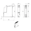
| Width | 50 mm |
| Height | 300 mm |
| Depth | 226 mm; 270 mm with spacer (included in scope of supply) |
Weights
| Weight, approx. | 2 400 g |
Other
| Note: | The SIMATIC Drive Controller deviates from the usual SIMATIC S7-1500 ambient conditions and specifications as well as the available approvals and certificates because of the drive design. For details, see the SIMATIC Drive Controller device and system manual. Operation is without fan. |
Downloads & documentation
Official documents from Siemens, downloaded directly from the manufacturer.
Data sheets & manuals
6ES7615-7DF10-0AB0: frequently asked questions
When can 6ES7615-7DF10-0AB0 be shipped?
6ES7615-7DF10-0AB0 is sourced on request — request a quote and we'll confirm the exact availability and shipping timeline for this specific unit.
Can I pick up 6ES7615-7DF10-0AB0 in person?
Local pickup from our Groningen, Netherlands warehouse may be possible — contact us before ordering to check availability and arrange a collection time.
Is express delivery available?
Yes — mention it when you request a quote for 6ES7615-7DF10-0AB0 and we'll include express shipping options in our reply.
My factory is down and I need this urgently — can you help?
For a critical breakdown, contact us directly at +31 (0)50-7110348 or sales@partnerplc.com — we can look into same-day courier or dedicated taxi/hotshot delivery for 6ES7615-7DF10-0AB0, subject to availability and destination.
More Siemens parts


Siemens 6ES7615-7DF10-0AB0Price and lead time confirmed within 1 business day
Request a Quote