




.svg&w=240)


















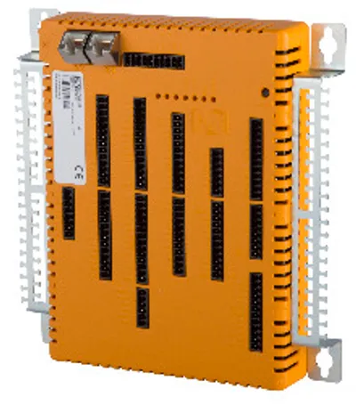
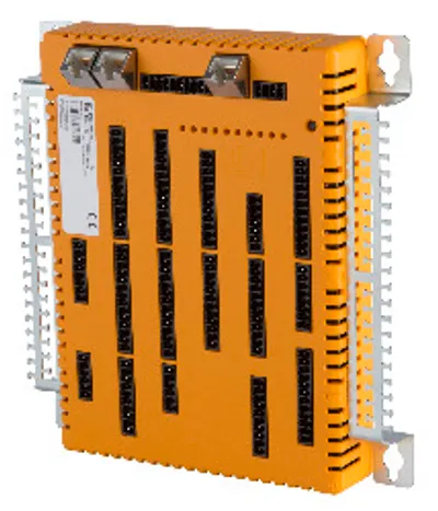
B&R XEPIMC100.02
I/O module, 35 digital inputs, 6 analog inputs
- MPN
- XEPIMC100.02
Price and lead time confirmed within 1 business day
Request a Quote
- 12-month warranty (new) · 3-month (used/refurbished)
- 30-day returns, no restocking fee on unused parts
- Ships via



What is the B&R XEPIMC100.02?
CPU I/O board, ARM Cortex-A9, 667 MHz, 2 GB flash memory, 512 MB DDR3 SDRAM, 64 kB FRAM, 24 VDC, 2x Ethernet interface,1x CAN bus, 1x RS485 interface, 1x USB 2.0 interface, 35 digital inputs, 24 VDC, sink/source, 2 event counters or gate time / period measurement, 33 digital outputs, 24 VDC, 2 A (50%), 12 digital outputs, 24 VDC, 0.5 A, 2 PWM outputs, 3 A, 8 thermocouple inputs J, K, S, N, 4 analog inputs for potentiometers, 0 to 10 V, 0 to 20 mA, 4.5 V, 14-bit, 2 analog inputs ±10 V, 14-bit, 4 analog outputs, ±10 V, 12-bit
Specifications
Short description
| I/O module | 35 digital inputs, 6 analog inputs, 45 digital outputs, 4 analog outputs, 8 thermocouples, 2 PWM outputs |
| Interfaces | 2x Ethernet, 1x CAN bus, 1x RS485 interface, 1x USB |
General information
| System requirements – Automation Studio | 4.5.01 or later |
| System requirements – Automation Runtime | B4.53 or later |
| LEDs – Quantity | 7 |
| LEDs – State | Supply voltage OK, operating state, module status, Ethernet, CAN, RS485 |
| Controller redundancy – Master capability | No |
| Support – ACOPOS support | No |
| Support – Visual Components support | No |
| Support – Safety support | No |
| Certifications – CE | Yes |
| Certifications – CRA (Cyber Resilience Act) | In preparation |
| B&R ID code | 0xF733 |
| Cooling | Passive |
| Power button | No |
| Reset button | Yes |
| Buzzer | No |
| Electrical isolation | Thermocouples, Ethernet 1 (IF2) and Ethernet 2 (IF3) isolated from each other and from other interfaces; Power supply not isolated from channel, and channel not isolated from channel |
Controller
| Processor – Data code | 24 kB |
| Processor – Program code | 32 kB |
| Processor – Type | ARM Cortex-A9 |
| Processor – Clock frequency | 667 MHz |
| Processor – L2 cache | 256 kB |
| Standard memory – RAM | 512 MB DDR3 SDRAM |
| Application memory – Guaranteed | 40 TB |
| Application memory – Results for 5 years | 21.9 GB/day |
| Application memory – Type | 2 GB eMMC flash memory |
| Application memory – Data retention | 10 years |
| Application memory – Guaranteed erase/write cycles | 20,000 |
| Application memory – Error-correcting code (ECC) | Yes |
| Bootloader | Automation Runtime: A4.11 |
| CompactFlash slot | 0 |
| Real-time clock | Yes, 1 s resolution, >±10 ppm accuracy at 25°C (note: The real-time clock is backed up for approx. 1000 hours @ 25°C by a gold foil capacitor. The gold foil capacitor is completely charged after 3 continuous hours of operation.) |
| FPU | Yes |
| Mode/Node switches | No |
| Remanent variables | 64 kB FRAM, retention >10 years (note: The memory size for remanent variables is configurable in Automation Studio.) |
| Shortest task class cycle time | 1 ms |
| Typical instruction cycle time | 0.01 μs |
| Temperature cutoff | Yes |
Interfaces
| Interface IF2 – Physical layer | 10BASE-T/100BASE-TX |
| Interface IF2 – Half-duplex | Yes |
| Interface IF2 – Full-duplex | Yes |
| Interface IF2 – Autonegotiation | Yes |
| Interface IF2 – Auto-MDI/MDIX | Yes |
| Interface IF2 – Connection designation | X2 Ethernet1 |
| Interface IF2 – Type | Ethernet |
| Interface IF2 – Variant | 1x RJ45 shielded |
| Interface IF2 – Line length | Max. 100 m between 2 nodes (segment length) |
| Interface IF2 – Max. transfer rate | 10/100 Mbit/s |
| Interface IF3 – Physical layer | 10BASE-T/100BASE-TX |
| Interface IF3 – Half-duplex | Yes |
| Interface IF3 – Full-duplex | Yes |
| Interface IF3 – Autonegotiation | Yes |
| Interface IF3 – Auto-MDI/MDIX | Yes |
| Interface IF3 – Connection designation | X3 Ethernet2 |
| Interface IF3 – Type | Ethernet |
| Interface IF3 – Variant | 1x RJ45 shielded |
| Interface IF3 – Line length | Max. 100 m between 2 nodes (segment length) |
| Interface IF3 – Max. transfer rate | 10/100 Mbit/s |
| Interface IF4 – Connection designation | X1 USB1 |
| Interface IF4 – Type | USB 2.0 |
| Interface IF4 – Variant | Type A |
| Interface IF4 – Current-carrying capacity | 0.5 A |
| Interface IF6 – Connection designation | X4 CAN1 |
| Interface IF6 – Type | CAN bus |
| Interface IF6 – Variant | Connection made using 0TB1110.9000 |
| Interface IF6 – Transfer rate | Max. 1 Mbit/s |
| Interface IF8 – Connection designation | X4 RS485 |
| Interface IF8 – Type | RS485 |
| Interface IF8 – Variant | Connection made using 0TB1110.9000 |
| Interface IF8 – Transfer rate | Max. 115.2 kbit/s |
Digital inputs
| Switching threshold – Low | <5 V |
| Switching threshold – High | >15 V |
| Quantity | 33 inputs + 2 counter inputs |
| Nominal voltage | 24 VDC |
| Input voltage | 24 VDC ±20% |
| Input current at 24 VDC | 3.2 mA |
| Additional functions | Event counter, gate and period measurement |
| Circuit | Sink or source |
| Input delay | Counter inputs 1 to 2: <4 µs; Inputs 3 to 33: <1 ms |
Event counters
| Quantity | 2 |
| Signal form | Square wave pulse |
| Evaluation | Positive or negative edge, cyclic counter |
| Input frequency | Max. 100 kHz |
| Pulse length | >4 µs |
| Counter size | 16-bit |
| Supported inputs | Input 1: Counter 1; Input 2: Counter 2 |
Gate time measurement
| Counter frequency – Internal | 48 MHz, 12 MHz, 3 MHz, 750 kHz |
| Counter frequency – External | Max. 100 kHz (note: If channel 1 is configured for an external counter frequency, then input 2 is used for supplying the external counter frequency.) |
| Quantity | 2 |
| Signal form | Square wave pulse |
| Evaluation | Positive or negative edge |
| Counter size | 16-bit |
| Input frequency | Max. 100 kHz |
| Length of pause between pulses | 10 µs |
| Pulse length | 10 µs |
| Supported inputs | Input 1: Counter 1; Input 2: Counter 2 |
Period measurement
| Counter frequency – Internal | 48 MHz, 12 MHz, 3 MHz, 750 kHz |
| Counter frequency – External | Max. 100 kHz (note: If channel 1 is configured for an external counter frequency, then input 2 is used for supplying the external counter frequency.) |
| Quantity | 2 |
| Signal form | Square wave pulse |
| Supported inputs | Input 1: Counter 1; Input 2: Counter 2 |
| Input frequency | Max. 100 kHz |
| Evaluation | Positive or negative edge |
| Counter size | 16-bit |
Analog inputs
| Output format – Data type | INT |
| Output format – Voltage | Inputs 1 and 2: INT 0x8000 - 0x7FFF / 1 LSB = 0x0004 = 1.22 mV; Inputs 3 to 6: INT 0x0000 - 0x7FFF / 1 LSB = 0x0004 = 1.22 mV |
| Output format – Current | Inputs 3 to 6: INT 0x0000 - 0x7FFF / 1 LSB = 0x0008 = 4.88 µA |
| Max. error – Gain | 0.1% (note: Based on the current measured value. To avoid interference by switching DOs or PWM, it is recommended that the power supply (X4) be isolated from the DO/DI and PWM power supplies. With this isolated power supply, any analog sensors and actuators can/should also be operated.) |
| Max. error – Offset | 0.025% (note: Based on the measurement range. To avoid interference by switching DOs or PWM, it is recommended that the power supply (X4) be isolated from the DO/DI and PWM power supplies. With this isolated power supply, any analog sensors and actuators can/should also be operated.) |
| Max. error – Gain | 0.12% (note: Based on the current measured value. To avoid interference by switching DOs or PWM, it is recommended that the power supply (X4) be isolated from the DO/DI and PWM power supplies. With this isolated power supply, any analog sensors and actuators can/should also be operated.) |
| Max. error – Offset | 0.05% (note: Based on the measurement range. To avoid interference by switching DOs or PWM, it is recommended that the power supply (X4) be isolated from the DO/DI and PWM power supplies. With this isolated power supply, any analog sensors and actuators can/should also be operated.) |
| Max. gain drift – Voltage | 0.006%/°C (note: Based on the current measured value. To avoid interference by switching DOs or PWM, it is recommended that the power supply (X4) be isolated from the DO/DI and PWM power supplies. With this isolated power supply, any analog sensors and actuators can/should also be operated.) |
| Max. gain drift – Current | 0.009%/°C (note: Based on the current measured value. To avoid interference by switching DOs or PWM, it is recommended that the power supply (X4) be isolated from the DO/DI and PWM power supplies. With this isolated power supply, any analog sensors and actuators can/should also be operated.) |
| Max. offset drift – Voltage | 0.002%/°C (note: Based on the measurement range. To avoid interference by switching DOs or PWM, it is recommended that the power supply (X4) be isolated from the DO/DI and PWM power supplies. With this isolated power supply, any analog sensors and actuators can/should also be operated.) |
| Max. offset drift – Current | 0.004 %/°C (note: Based on the measurement range. To avoid interference by switching DOs or PWM, it is recommended that the power supply (X4) be isolated from the DO/DI and PWM power supplies. With this isolated power supply, any analog sensors and actuators can/should also be operated.) |
| Input filter – Cutoff frequency | Inputs 1 and 2: 1 kHz; Inputs 3 to 6: 10 kHz |
| Input filter – Slope | 60 dB |
| Input | Inputs 1 and 2: ±10 V; Inputs 3 to 6: 0 to 10 V, 0 to 20 mA or 0 to 100% (U pot ) |
| Input type | Inputs 1 and 2: Differential input; Inputs 3 to 6: Single-ended input |
| Digital converter resolution | 14-bit |
| Input impedance in signal range | 10 MΩ |
| Current channel load | <400 Ω |
| Input protection | Protection against wiring with supply voltage |
| Supply voltage U Pot for potentiometer | 4.5 V / Max. 50 mA |
| Measurement range | 0.5 to 10 kΩ |
Thermocouple temperature inputs
| Measurement range – FeCuNi: Type J | -210 to 1200°C |
| Measurement range – NiCrNi: Type K | -270 to 1372°C |
| Measurement range – NiCrSi: Type N | -270 to 1300°C |
| Measurement range – PtRhPt: Type S | -50 to 1768°C |
| Measurement range – Voltage | ±70 mV |
| Resolution – Sensor temperature | 0.1°C/LSB |
| Resolution – Voltage | 2.136 µV/LSB |
| Basic accuracy – Type J: Fe-CuNi | ±0.14% at 25°C (note: Based on the measurement range.) |
| Basic accuracy – Type K: NiCr-Ni | ±0.18% at 25°C (note: Based on the measurement range.) |
| Basic accuracy – Type N: NiCrSi-NiSi | ±0.16% at 25°C (note: Based on the measurement range.) |
| Basic accuracy – Type S: PtRh10-Pt | ±0.34% at 25°C (note: Based on the measurement range.) |
| Terminal temperature compensation – Internal | Yes |
| Terminal temperature compensation – Basic accuracy at 25°C not taking Pt1000 sensor into account | ±2°C after 10 minutes |
| Quantity | 8 |
| Digital converter resolution | 16-bit |
| Output format | INT |
Digital outputs
| Actuator power supply – Supply | External |
| Actuator power supply – Fuse | No internal fuse, the power supply of the outputs of each connector must be protected using a separate fuse of max. 15 A. |
| Quantity | 45 |
| Nominal output current | Screw clamp terminal blocks X12, X13 and X15:; Per output: 2 A; Per group: 2 A; Per screw clamp terminal block: 11 A; Screw clamp terminal blocks X14 and X16:; Per output: 0.5 A (note: Group: Two adjacent channels DOx and DOx+1, where x can be any odd number between 1 and 31.) |
| Output circuit | Sink |
| Output protection | Short circuit and overload protection |
| Switching frequency (resistive load) | Max. 100 Hz |
| Switching delay | Max. 500 µs |
| Type | Low-side driver (Sink) |
| Supply voltage | Separately for each connector: 12 to 24 VDC ±20% |
PWM output
| Load – Resistive load | ≥8 Ω |
| Load – Inductive load | ≤10 mH |
| PWM pulse width – PWM mode | 15-bit + sign; ≥1 µs |
| PWM pulse width – Current mode | 15-bit + sign |
| Quantity | 2 |
| Type | Push/Pull |
| Supply voltage (permissible range) | External, 11 to 28 VDC |
| Nominal current | 3 A |
| Maximum load current | 3.5 A / output (note: Channel cut off if exceeded (overcurrent protection)) |
| PWM frequency | 15 Hz to 50 kHz |
| Output protection | Reverse polarity protection for supply voltage, must be protected externally |
| Configurable dither | Amplitude (8-bit), frequency (2 to 500 Hz) |
| Period duration resolution | 16-bit |
Analog outputs
| Max. error – Gain | 0.080%, based on the current output value |
| Max. error – Offset | 0.050%, based on the entire output range |
| Output format – Data type | INT |
| Output format – Voltage | INT 0x8000 - 0x7FFF / 1 LSB = 0x0010 = 4.88 mV |
| Range of values – 10 V | 0x7FFF |
| Range of values – 0 V | 0x0000 |
| Range of values – -10 V | 0x8000 |
| Quantity | 4 |
| Output | ±10 V |
| Digital converter resolution | 12-bit |
| Switch on/off behavior | Internal enable relay, for startup |
| Output protection | Protection against wiring with supply voltage, short-circuit proof |
| Max. load per output | ±10 mA (load ≥1 kΩ) |
| Max. gain drift | 0.08%, based on the current output value |
| Max. offset drift | 0.05%, based on the entire output range |
| Error caused by load change | 0.015% from 10 MΩ → 1 kΩ, resistive |
| Nonlinearity | 0.025%, based on the output range |
Power supply unit
| Voltage range | 24 VDC ±25% |
| Power consumption | 3.5 W |
| Voltage monitoring | Yes |
Operating conditions
| Mounting orientation – Horizontal | No |
| Mounting orientation – Vertical | Yes |
| Pollution degree per EN 60664-1 | 2 |
Ambient conditions
| Temperature – Operation | 0 to 50°C |
| Temperature – Storage | -40 to 85°C |
| Temperature – Transport | -40 to 85°C |
| Relative humidity – Operation | 10 to 90%, non-condensing |
| Relative humidity – Storage | 5 to 95%, non-condensing |
| Relative humidity – Transport | 5 to 95%, non-condensing |
Mechanical properties
| Dimensions – Width | 190 mm |
| Dimensions – Height | 198 mm |
| Dimensions – Depth | 31 mm |
| Module dimensions including mounting plates | 190 x 198 x 31 mm (W x H x D) |
Accessories
Required accessories (order separately)
| XEPIMA419 | Miscellaneous — SMARTMOLD I/O connector set (112 I/Os) |
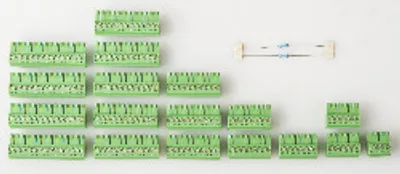
| XEPIMA200 | Miscellaneous — SMARTMOLD I/O connector set (119 I/Os) screw clamp terminal blocks |
| XEPIMA100 | Miscellaneous — SMARTMOLD I/O connector set (100 I/Os) screw clamp terminal blocks |
Optional accessories (2)
| XEPIMA200.01 | Miscellaneous — SMARTMOLD I/O connector set (119 I/Os) cage clamp terminals |
| XEPIMA100.01 | Miscellaneous — SMARTMOLD I/O connector set (100 I/Os) cage clamp terminals |
Downloads & documentation
Official documents from B&R, downloaded directly from the manufacturer.
Data sheets & manuals
XEPIMC100.02: frequently asked questions
When can XEPIMC100.02 be shipped?
XEPIMC100.02 is sourced on request — request a quote and we'll confirm the exact availability and shipping timeline for this specific unit.
Can I pick up XEPIMC100.02 in person?
Local pickup from our Groningen, Netherlands warehouse may be possible — contact us before ordering to check availability and arrange a collection time.
Is express delivery available?
Yes — mention it when you request a quote for XEPIMC100.02 and we'll include express shipping options in our reply.
My factory is down and I need this urgently — can you help?
For a critical breakdown, contact us directly at +31 (0)50-7110348 or sales@partnerplc.com — we can look into same-day courier or dedicated taxi/hotshot delivery for XEPIMC100.02, subject to availability and destination.
More B&R parts

B&R XEPIMC100.02Price and lead time confirmed within 1 business day
Request a Quote