
























B&R X90RO440.04-S1
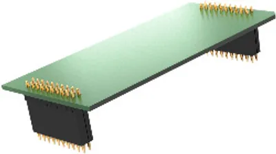
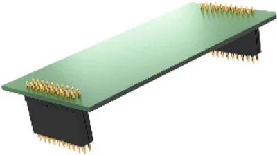
I/O module, 4 relays with 1 normally open contact each
- MPN
- X90RO440.04-S1
Price and lead time confirmed within 1 business day
Request a Quote
- 12-month warranty (new) · 3-month (used/refurbished)
- 30-day returns, no restocking fee on unused parts
- Ships via



- 100% positive eBay feedback
What is the B&R X90RO440.04-S1?
9 to 32 VDC
4 safe relay outputs
Output type "Relay"
Nominal output current 2x 2 A and 2x 4 A
Normally open contact
Single-channel isolated outputs
X2X Link
The relay option board provides 4 additional safe relay outputs. Communication to the mainboard is made possible via X2X Link.
The modules can be used for controlling floating actuators in safety-related applications up to PL e or SIL 3. Safety relays are installed within the module. The positively driven feedback contacts are evaluated within the module. The safe digital output modules have a start interlock on error in the event of network errors.
Specifications
Short description
| I/O module | 4 relays with 1 normally open contact each, 9 to 32 VDC / 2 and 4 A |
General information
| System requirements – Automation Studio | 4.7 or later (note: The specified minimum requirements are automatically met when using recommended mapp Safety Technology Package 5.7 or later. In addition, the system requirements of the mapp Safety Technology Package must be taken into account (see Automation Help).) |
| System requirements – Automation Runtime | 4.7 or later (note: The specified minimum requirements are automatically met when using recommended mapp Safety Technology Package 5.7 or later. In addition, the system requirements of the mapp Safety Technology Package must be taken into account (see Automation Help).) |
| System requirements – mapp Technology Package | mapp Safety 5.12 and later: (note: The specified minimum requirements are automatically met when using recommended mapp Safety Technology Package 5.7 or later. In addition, the system requirements of the mapp Safety Technology Package must be taken into account (see Automation Help).) |
| Diagnostics – Module run/error | Yes, using software |
| Diagnostics – Outputs | Yes, using software |
| Power consumption – Bus | 0.26 W |
| Power consumption – Internal I/O | 1.65 W |
| Certifications – UN ECE-R10 | Yes |
| Certifications – CE | Yes |
| Certifications – UKCA | Yes |
| Certifications – CRA (Cyber Resilience Act) | In preparation |
| B&R ID code | 0xFB3D |
| Status indicators | - |
| Power consumption | Max. 2 W |
| Max. I/O cycle time | 1 ms |
| Additional power dissipation caused by actuators (resistive) [W]Mechanical and electrical configuration" in the X20 system user's manual."> | +3.2 (note: Number of outputs x Contact resistance x Nominal output current 2 . For a calculation example, see section) |
Safety characteristics
| EN ISO 13849-1:2015 – MTTFD per channel | 100 years if the relay channel is used individually, 390 years if 2 relay channels are connected in series |
| EN ISO 13849-1:2015 – Mission time | Max. 20 years |
| IEC 61508:2010,; EN 62061:2013 – Module | <2.7*10 -7 if the relay channel is used individually, <5.4*10 -9 if 2 relay channels are connected in series |
| IEC 61508:2010,; EN 62061:2013 – openSAFETY wired | Negligible |
| IEC 61508:2010,; EN 62061:2013 – openSAFETY wireless | <1*10 -14 * Number of openSAFETY packets per hour |
| IEC 61508:2010,; EN 62061:2013 – PFD per channel | <5.6*10 -4 if the relay channel is used individually, <1*10 -4 if 2 relay channels are connected in series |
| IEC 61508:2010,; EN 62061:2013 – Proof test interval (PT) | 20 years |
| Safe relay channels – DC1, 24 VDC | 2 A / 1,800,000 ; 4 A / 1,000,000 |
| Safe relay channels – DC13, 24 VDC | 2 A / 121,400 ; 4 A / 120,000 |
| Safe relay channels – Category | KAT 1 if the relay channel is used individually, KAT 4 if 2 relay channels are connected in series |
| Safe relay channels – PL | PL c if the relay channel is used individually, PL e if 2 relay channels are connected in series |
| Safe relay channels – SIL CL | SIL 1 if the relay channel is used individually, SIL 3 if 2 relay channels are connected in series (note: The related danger notices in the technical data sheet must also be observed.) |
I/O power supply
| Voltage range | 9 to 32 VDC |
Relay outputs
| Switching delay – 0 → 1 | <50 ms |
| Switching delay – 1 → 0 | <20 ms |
| Service life – Mechanical | Min. 1 x 10 7 ops. |
| Service life – Electrical | Min. 1 x 10 5 ops. (at 4 A / 32 VDC) (note: With 6 switching operations per minute and an on/off time of 1 s to 9 s.) |
| Protective circuit – Internal | - |
| Protective circuit – External | Relays 1 and 2: External fuse 2 A; Relays 3 and 4: External fuse 4 A (note: 2 A and 4 A fuses: gL/gG fuse or melting fuse with max. 40 A²s.) |
| Max. switching capacity – DC1 | Relays 1 and 2: 24 VDC / 2 A; Relays 3 and 4: 24 VDC / 4 A |
| Max. switching capacity – DC13 | Relays 1 and 2: 24 VDC / 2 A; Relays 3 and 4: 24 VDC / 4 A |
| Quantity | 4 |
| Variant | Relay / Normally open contact, internal high-side and low-side control |
| Nominal output current | Relays 1 and 2: 2 A; Relays 3 and 4: 4 A |
| Diagnostic status | Contact position determined by positively driven contacts |
| Max. switching frequency | 10 Hz |
| Contact resistance (without terminal block) | 80 mΩ |
| Contact service life | See "Contact service life". |
| Switching voltage range | 5 to 32 VDC |
| Switching current range | 1 mA to 4 A |
| Max. inrush current | 20 A for 25 ms, max. 1x per minute |
| Overvoltage category per EN 60664-1 | II |
Electrical properties
| Electrical isolation | Channel isolated from channel and bus |
Operating conditions
| Mounting orientation – Any | Yes |
| Degree of protection per EN 60529 | IP66, IP69K (note: Depends on the CPU (for additional details, see the data sheet for the X90 mobile CPU).) |
Ambient conditions
| Temperature – Horizontal mounting orientation | -40 to 75°C housing surface (note: Depends on the CPU (for additional details, see the data sheet for the X90 mobile CPU).) |
| Temperature – Vertical mounting orientation | -40 to 75°C housing surface (note: Depends on the CPU (for additional details, see the data sheet for the X90 mobile CPU).) |
| Temperature – Storage | -40 to 85°C |
| Temperature – Transport | -40 to 85°C |
| Relative humidity – Operation | 5 to 100%, condensing |
| Relative humidity – Storage | 5 to 100%, condensing |
| Relative humidity – Transport | 5 to 100%, condensing |
Mechanical properties
| Dimensions – Width | 47 mm |
| Dimensions – Length | 95 mm |
Downloads & documentation
Official documents from B&R, downloaded directly from the manufacturer.
Data sheets & manuals
Certificates (8)
- EU Data Act - X90 - Connected Product Information Notice
- EU Declaration FS mobile automation X90
- EU Declaration Industrial sector X90
- EU Declaration Mobile machinery X90
- M6A 041745 0013 TÜV Süd FS Certificate mapp Safety
- M6A 041745 0015 TÜV Süd FS Certificate X90 mobile
- UK Declaration Industrial sector X90
- UN ECE-R10
X90RO440.04-S1: frequently asked questions
When can X90RO440.04-S1 be shipped?
X90RO440.04-S1 is sourced on request — request a quote and we'll confirm the exact availability and shipping timeline for this specific unit.
Can I pick up X90RO440.04-S1 in person?
Local pickup from our Groningen, Netherlands warehouse may be possible — contact us before ordering to check availability and arrange a collection time.
Is express delivery available?
Yes — mention it when you request a quote for X90RO440.04-S1 and we'll include express shipping options in our reply.
My factory is down and I need this urgently — can you help?
For a critical breakdown, contact us directly at +31 (0)50-7110348 or sales@partnerplc.com — we can look into same-day courier or dedicated taxi/hotshot delivery for X90RO440.04-S1, subject to availability and destination.
More B&R parts



B&R X90RO440.04-S1Price and lead time confirmed within 1 business day
Request a Quote