




.svg&w=240)


















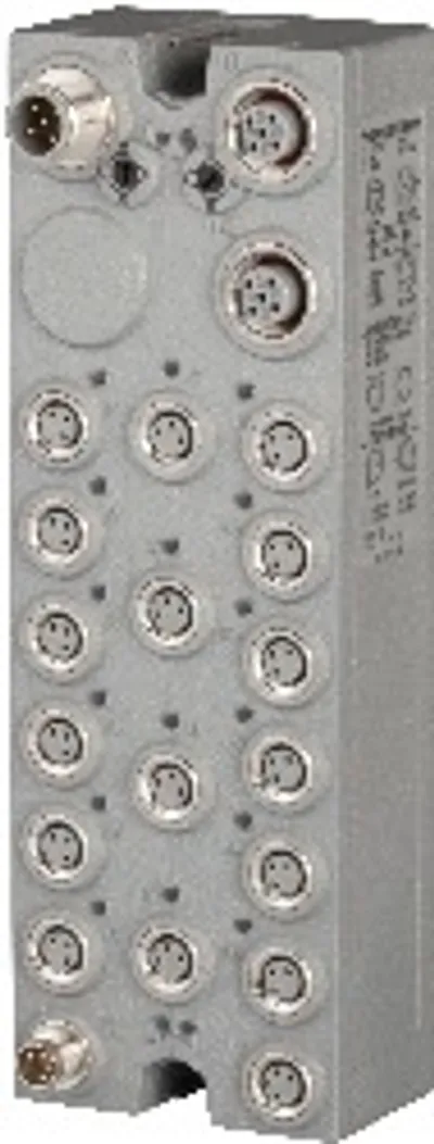
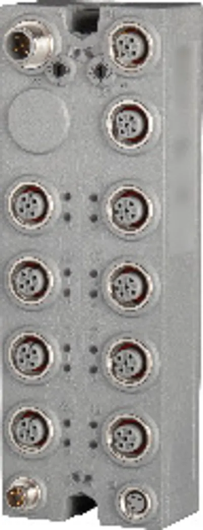
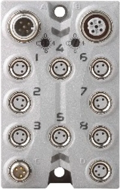
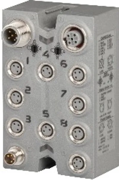
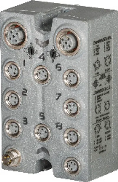
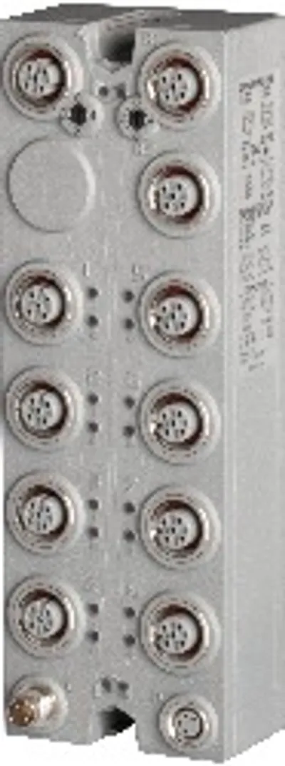
B&R X67BC81RT.L12
Bus controller, POWERLINK (V1/V2) controlled node
- MPN
- X67BC81RT.L12
- Category
- Bus controller modules
Price and lead time confirmed within 1 business day
Request a Quote
- 12-month warranty (new) · 3-month (used/refurbished)
- 30-day returns, no restocking fee on unused parts
- Ships via



What is the B&R X67BC81RT.L12?
POWERLINK
reACTION Technology module
Integrated hub for efficient cabling
4 digital inputs
5 digital channels, configurable as inputs or outputs
2 analog inputs ±10 V
1 analog input ±10 V
1 ABR incremental encoder input 5 V
5 V and 24 V encoder power supply integrated in the encoder connector
I/O configuration and firmware update via the fieldbus
Integrated connection to local expansions via X2X Link for 250 additional modules
Cycle time configurable starting at 200 µs for local expansions
The bus controller makes it possible to connect X2X Link I/O nodes to POWERLINK. It is also possible to operate the X2X Link cycle synchronously 1:1 or synchronous to POWERLINK using a prescaler.
Additional X2X Link I/O nodes (X67 modules or other modules based on X2X Link) can be connected using the integrated X2X Link connection. Mechanically, POWERLINK is connected via an IP67-rated standard D-coded M12 Ethernet connector.
POWERLINK is a standard protocol for Fast Ethernet equipped with hard real-time characteristics. The POWERLINK Standardization Group (EPSG) ensures that the standard remains open and is continually developed:: www.ethernet-powerlink.org .
Ultrafast reACTION Technology makes it possible to control I/O channels with response times down to 1 μs. All of the commands that can be used for reACTION programs are provided as function blocks in special libraries (e.g. AsIORTI) . Programming using the standard Function Block Diagram (FBD) editor in Automation Studio is compliant with IEC 61131-3 .
Specifications
Short description
| Bus controller | POWERLINK (V1/V2) controlled node |
General information
| B&R ID code – Bus controller | 0xE2DC |
| B&R ID code – Internal I/O module | 0xE2DF |
| Diagnostics – Outputs | Yes, using LED status indicator and software |
| Diagnostics – I/O power supply | Yes, using LED status indicator and software |
| Support – Dynamic node allocation (DNA) | Yes |
| Support – reACTION-capable I/O channels | Yes |
| Connection type – Fieldbus | M12, D-coded |
| Connection type – X2X Link | M12, B-coded |
| Connection type – Inputs/Outputs | M12, 5-pin, A-coded |
| Connection type – Encoder | M12, 12-pin, A-coded |
| Connection type – I/O power supply | M8, 4-pin |
| Power consumption – Fieldbus | 4.6 W |
| Power consumption – Internal I/O | 6 W |
| Power consumption – X2X Link power supply | 19.6 W at maximum power output for connected I/O modules |
| Application memory – Type | 16 Mbit flash memory |
| Application memory – Data retention | 20 years at 55°C |
| Application memory – Guaranteed erase/write cycles | 100,000 |
| Certifications – CE | Yes |
| Certifications – UKCA | Yes |
| Certifications – CRA (Cyber Resilience Act) | In preparation |
| Certifications – ATEX | Zone 2, II 3G Ex nA IIA T5 Gc; IP67, Ta = 0 - Max. 60°C; TÜV 05 ATEX 7201X |
| Certifications – UL | cULus E115267; Industrial control equipment |
| Certifications – HazLoc | cCSAus 244665; Process control equipment; for hazardous locations; Class I, Division 2, Groups ABCD, T5 |
| Inputs/Outputs | 4 digital inputs, 2 digital channels, configurable as inputs or outputs using software, 2 analog inputs, 1 analog output, 1 ABR input, also usable as 5 V differential inputs/outputs, inputs with special function |
| Insulation voltage between channel and bus | 500 V eff |
| Nominal voltage | 24 VDC |
| Status indicators | I/O function per channel, supply voltage, bus function |
| Power output | 15 W X2X Link power supply for I/O modules |
Interfaces
| Transfer – Physical layer | 100BASE-TX |
| Transfer – Half-duplex | Yes |
| Transfer – Full-duplex | No |
| Transfer – Autonegotiation | Yes |
| Transfer – Auto-MDI/MDIX | Yes |
| Min. cycle time – Fieldbus | 200 μs (note: The minimum cycle time specifies how far the bus cycle can be reduced without communication errors occurring.) |
| Min. cycle time – X2X Link | 200 μs (note: The minimum cycle time specifies how far the bus cycle can be reduced without communication errors occurring.) |
| Fieldbus | POWERLINK (V1/V2) controlled node |
| Variant | 2x M12 circular connector (hub), 2x female connector on module |
| Line length | Max. 100 m between 2 stations (segment length) |
| Transfer rate | 100 Mbit/s |
| Hub propagation delay | 0.96 to 1 µs |
| Synchronization between bus systems possible | Yes |
Encoder power supply connector 8
| 5 VDC | Module-internal, max. 0.3 A summation current |
| 24 VDC | Module-internal, max. 0.5 A summation current |
I/O power supply
| Power consumption – Sensor/Actuator power supply | Max. 12 W (note: The power consumption of the sensors and actuators connected to the module is not permitted to exceed 12 W.) |
| Nominal voltage | 24 VDC |
| Voltage range | 18 to 30 VDC |
| Integrated protective function | Reverse polarity protection |
Sensor/Actuator power supply
| Voltage | I/O power supply minus voltage drop for short-circuit protection |
| Voltage drop for short-circuit protection at 0.5 A | Max. 2 VDC |
| Summation current | Max. 0.5 A |
| Short-circuit proof | Yes |
ABR incremental encoder
| Quantity | 1 |
| Encoder inputs | DI 5 to DI 7, 5 V, symmetrical; DI 1 to DI 4 and DI 8 to DI 9, 24 V, asymmetrical |
| Counter size | 32-bit |
| Input frequency | DI 1 to DI 7: 250 kHz; DI 8 and DI 9: 100 kHz |
| Evaluation | 4x |
| Encoder power supply | 5 V: Module-internal, max. 0.3 A; 24 V: Module-internal, max. 0.5 A |
| Overload characteristics of encoder power supply | Short-circuit proof, overload-proof |
Digital inputs 5 VDC
| Input filter – Hardware | No input filter |
| Input filter – Software | Default 200 ns, configurable between 200 ns and 5 ms in 20 ns intervals |
| Nominal voltage | 5 VDC |
| Input circuit | Differential |
| Insulation voltage between encoder and bus | 500 V eff |
Digital inputs 24 VDC
| Input filter – Hardware | ≤50 ns |
| Input filter – Software | Default 200 ns, configurable between 200 ns and 5 ms in 20 ns intervals |
| Input current at 24 VDC – Channel 1 and 2 | Typ. 9 mA |
| Input current at 24 VDC – Channel 3 and 4 | Typ. 3 mA |
| Input current at 24 VDC – Channel 8 and 9 | Typ. 1 mA |
| Input resistance – Channel 1 and 2 | Typ. 3 kΩ |
| Input resistance – Channel 3 and 4 | Typ. 8 kΩ |
| Input resistance – Channel 8 and 9 | Typ. 40 kΩ |
| Switching threshold – Low | <5 VDC |
| Switching threshold – High | <15 VDC |
| Nominal voltage | 24 VDC |
| Input characteristics per EN 61131-2 | Type 1 (note: Only channels 1 to 4) |
| Input circuit | Sink |
| Input voltage | 24 VDC -15/+20% |
| Sensor power supply | 0.5 A summation current |
| Insulation voltage between channel and bus | 500 V eff |
Analog inputs
| Output of digital value during overload – Undershoot | 0x8001 |
| Output of digital value during overload – Overshoot | 0x7FFF |
| Max. error – Gain | 0.1% (note: Based on the current output value.) |
| Max. error – Offset | 0.05% (note: Based on the total output value.) |
| Max. drift at 25°C – Gain | 0.01%/°C (note: Based on the current output value.) |
| Max. drift at 25°C – Offset | 0.0075% / °C (note: Based on the total output value.) |
| Input | ±10 V |
| Input type | Single-ended |
| Digital converter resolution | 12-bit |
| Conversion time | 5 µs for both inputs |
| Output format | INT |
| Input protection | Protection against wiring with supply voltage |
| Open-circuit detection | Yes, using software |
| Reverse polarity protection | Yes |
| Permissible input signal | ±30 V |
| Conversion procedure | Successive approximation |
| Crosstalk between channels | -70 dB |
| Nonlinearity | <0.0062% (note: Based on the total output value.) |
| Insulation voltage between channel and bus | 500 V eff , 1 min |
Digital outputs 5 VDC
| Output protection | Short-circuit protection |
| Variant | Differential |
| Nominal voltage | 5 VDC |
| Output current | Max. 65 mADifferential output""> (note: For differential output voltage depending on the output current, see section) |
| Diagnostic status | Output monitoring |
| Switching frequency | Max. 500 kHz |
Digital outputs 24 VDC
| Switching frequency – Resistive load | Max. 100 kHz |
| Switching frequency – Inductive load | Max. 100 kHz |
| Switching delay – 0 → 1 | <1 µs |
| Switching delay – 1 → 0 | <1 µs |
| Nominal voltage | 24 VDC |
| Nominal output current | 0.4 A |
| Variant | Push/Pull |
| Output protection | Thermal shutdown in the event of overcurrent or short circuit |
| Braking voltage when switching off inductive loads | 50 VDC |
| Diagnostic status | Overload monitoring |
| Switch-on in the event of overload shutdown or short-circuit shutdown | Approx. 25 ms |
| Peak short-circuit current | <1 A |
| Switching voltage | 24 VDC (-15/+20%) |
| Insulation voltage between channel and bus | 500 V eff |
Analog outputs
| Max. error – Gain | 0.15% (note: Based on the current output value.) |
| Max. error – Offset | 0.05% (note: Based on the total output value.) |
| Short-circuit proof – Current limiting | ±40 mA |
| Short-circuit proof – To actuator or I/O power supply | Yes |
| Short-circuit proof – To GND | Yes |
| Max. error at 25°C and 10 kΩ load – Gain | 0.15% |
| Max. error at 25°C and 10 kΩ load – Offset | 0.05% |
| Output | ±10 V |
| Digital converter resolution | 12-bit |
| Conversion time | 2 µs |
| Settling time on output change over entire range | 2.5 µs |
| Switch on/off behavior | Internal enable relay for startup |
| Output protection | Short-circuit proof |
| Output format | Example: INT 0x8001 - 0x7FFF / 1 LSB = 0x0010 = 4.882 mV |
| Load per channel | Max. ±10 mA, load ≥1 kΩ |
| Output filter | First-order low-pass filter / cutoff frequency 2.5 kHz |
| Max. gain drift | 0.012%/°C (note: Based on the current output value.) |
| Max. offset drift | 0.001%/°C (note: Based on the total output value.) |
| Error caused by load change | Max. 0.01%, from 10 MΩ → 1 kΩ, resistive |
| Nonlinearity | <0.15% (note: Based on the total output value.) |
| Insulation voltage between channel and bus | 500 V eff , 1 min |
| Output response when the power supply is switched on/off | An enable relay is switched on at a defined value ≠ 0, default setting = 10 kΩ to GND |
Electrical properties
| Electrical isolation | Bus isolated from POWERLINK and channel; Channel not isolated from channel |
Operating conditions
| Mounting orientation – Any | Yes |
| Installation elevation above sea level – 0 to 2000 m | No limitation |
| Installation elevation above sea level – >2000 m | Reduction of ambient temperature by 0.5°C per 100 m |
| Degree of protection per EN 60529 | IP67 |
Ambient conditions
| Temperature – Operation | -25 to 60°C |
| Temperature – Derating | - |
| Temperature – Storage | -40 to 85°C |
| Temperature – Transport | -40 to 85°C |
Mechanical properties
| Dimensions – Width | 53 mm |
| Dimensions – Height | 155 mm |
| Dimensions – Depth | 42 mm |
| Torque for connections – M8 | Max. 0.4 Nm |
| Torque for connections – M12 | Max. 0.6 Nm |
| Weight | 320 g |
Downloads & documentation
Official documents from B&R, downloaded directly from the manufacturer.
Data sheets & manuals
CAD & dimension drawings
X67BC81RT.L12: frequently asked questions
When can X67BC81RT.L12 be shipped?
X67BC81RT.L12 is sourced on request — request a quote and we'll confirm the exact availability and shipping timeline for this specific unit.
Can I pick up X67BC81RT.L12 in person?
Local pickup from our Groningen, Netherlands warehouse may be possible — contact us before ordering to check availability and arrange a collection time.
Is express delivery available?
Yes — mention it when you request a quote for X67BC81RT.L12 and we'll include express shipping options in our reply.
My factory is down and I need this urgently — can you help?
For a critical breakdown, contact us directly at +31 (0)50-7110348 or sales@partnerplc.com — we can look into same-day courier or dedicated taxi/hotshot delivery for X67BC81RT.L12, subject to availability and destination.
More B&R parts
B&R X67BC81RT.L12Price and lead time confirmed within 1 business day
Request a Quote