























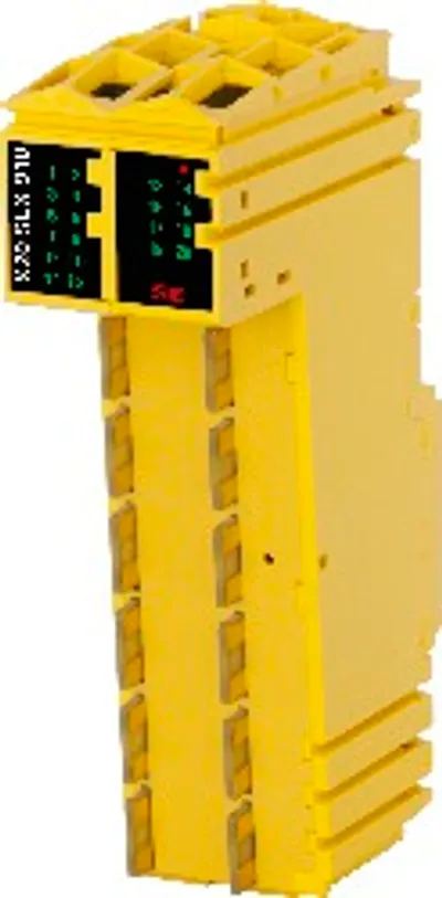
B&R X20SM1444-1
I/O module, 1 full bridge for controlling stepper motors
- MPN
- X20SM1444-1
- Category
- Motor controllers
Price and lead time confirmed within 1 business day
Request a Quote
- 12-month warranty (new) · 3-month (used/refurbished)
- 30-day returns, no restocking fee on unused parts
- Ships via



- 100% positive eBay feedback
What is the B&R X20SM1444-1?
1 stepper motor, 24 to 48 VDC ±25%, 5 A (10 A peak)
Resolution of current values at 1%
Boost, nominal and holding current separately configurable
Sensorless, load-dependent current control
Integrated motor detection
256 microsteps per step
Stall detection
Complete integration in Automation Studio and CNC applications
R+ and R- also configurable as digital inputs
Open circuit detection with 5 V differential ABR interface
Input ramp limit at max. 12.5 A
Function model "Ramp" based on CANopen communication profile DS402
The stepper motor module is used to control stepper motors with a nominal voltage of 24 to 48 VDC (±25%) at a motor current up to 5 A (10 A peak). ABR outputs R+ and R- can also be used as digital inputs.
Due to the individual adjustment of the coil currents, the motor is only operated with the current it actually needs. This simplifies the selection of the available motors and prevents unnecessary heating. Because this affects energy consumption and thermal load, the effects are positive on the service life of the complete system. Complete flexibility is achieved through the use of independently adjustable holding, maximum and nominal current values. The current for microsteps is automatically adjusted to the configured current values.
In addition, the module contains a sensorless, load-dependent current control. Depending on the operating situation and load, the module regulates the current downwards. Energy savings up to 75% are possible in this way.
The automatic motor identification system is an enormous help during standstills. The stepper motor modules can identify the connected motors using their coil characteristics and generate feedback in the form of an analog value. This makes it possible to detect not only wiring errors, but also incorrect motor types being used mistakenly. "Stall detection" is integrated to analyze the motor load. Detection of the stall is defined via a configurable threshold. This allows an overload or motor standstill to be detected precisely in many different types of applications.
Specifications
Short description
| I/O module | 1 full bridge for controlling stepper motors |
General information
| Diagnostics – Module run/error | Yes, using LED status indicator and software |
| Diagnostics – Output | Yes, using LED status indicator and software |
| Diagnostics – I/O power supply | Yes, using software |
| Power consumption – Bus | 0.1 W |
| Power consumption – Internal I/O | - |
| Power consumption – External I/O | At 18 VDC 0.54 W; At 24 VDC 0.6 W; At 40 VDC 0.76 W; At 60 VDC 0.97 W (note: Depends on the supplied voltage) |
| Certifications – CE | Yes |
| Certifications – UKCA | Yes |
| Certifications – CRA (Cyber Resilience Act) | In preparation |
| B&R ID code | 0xF3ED |
| Status indicators | I/O function per channel, operating state, module status |
| Additional power dissipation caused by actuators (resistive) [W] | At 1 A 0.31 W; At 2 A 0.574 W; At 3 A 0.848 W; At 4 A 1.1 W; At 5 A 1.4 W (note: Depends on the strength of the motor current) |
| Input current limiting | Max. 12.5 A |
| Type of signal lines | Shielded lines must be used for all signal lines. |
Motor output stage
| Module power supply – Supply | External |
| Module power supply – Fuse | Required line fuse: Max. 10 A, slow-blow |
| Quantity | 1 |
| Type | 2-phase bipolar stepper motor (full bridge) |
| Nominal voltage | 24 to 48 VDC ±25% (note: The tolerance value is composed of the voltage tolerances and permissible total AC voltage component with a peak value of 5% of the rated voltage.) |
| Nominal current | 5 A |
| Maximum current | 10 A for 1 sLet-through energy I2T"."> (note: See section) |
| DC bus capacitance | 300 µF |
| Step resolution | Max. 256 microsteps per step |
| Output protection | Reverse polarity protection on supply voltage |
Digital inputs
| Input filter – Hardware | <5 µs |
| Input filter – Software | - |
| Switching threshold – Low | <7.5 VDC |
| Switching threshold – High | >11.5 VDC |
| Quantity | 2 |
| Nominal voltage | 24 VDC |
| Input circuit | Sink |
| Connection type | 1-wire connections |
| Input resistance | Typ. 8.2 kΩ |
| Additional functions | Use as R+ and R- for ABR interface, ; quick stop and enable functionABR interface and digital inputs"."> (note: See section) |
| Open-circuit and short-circuit detection | No |
ABR incremental encoder
| Quantity | 1 |
| Encoder inputs | 5 V, symmetrical |
| Counter size | 16-bit |
| Input frequency | Max. 125 kHz |
| Evaluation | 4x |
| Open-circuit detection | Yes, differential detection |
Electrical properties
| Electrical isolation | Channel isolated from bus and channel isolated from I/O power supply |
Operating conditions
| Mounting orientation – Horizontal | Yes |
| Mounting orientation – Vertical | Yes |
| Installation elevation above sea level – 0 to 2000 m | No limitation |
| Installation elevation above sea level – >2000 m | Reduction of ambient temperature by 0.5°C per 100 m |
| Degree of protection per EN 60529 | IP20 |
Ambient conditions
| Temperature – Horizontal mounting orientation | -20 to +50°C |
| Temperature – Vertical mounting orientation | -20 to +40°C |
| Temperature – Derating | See section "Derating". |
| Temperature – Storage | -25 to +80°C |
| Temperature – Transport | -25 to +80°C |
| Relative humidity – Operation | 5 to 95%, non-condensing |
| Relative humidity – Storage | 5 to 95%, non-condensing |
| Relative humidity – Transport | 5 to 95%, non-condensing |
Mechanical properties
| Note | Order 1x terminal block X20TB12 separately.; Order 1x bus module X20BM31 separately. |
| Pitch | 25 +0.2 mm |
Accessories
Required accessories (order separately)
| X20BM31 | Bus modules — Bus module for double-width I/O modules; The internal I/O supply is interconnected The bus module serves as a basis for all double-width X2… |
| X20TB12 | Terminal blocks — Tool-free wiring with push-in technology; Simple wire release using lever; Ability to label each terminal; Plain text labeling also possibl… |
Downloads & documentation
Official documents from B&R, downloaded directly from the manufacturer.
Data sheets & manuals
CAD & dimension drawings
X20SM1444-1: frequently asked questions
When can X20SM1444-1 be shipped?
X20SM1444-1 is sourced on request — request a quote and we'll confirm the exact availability and shipping timeline for this specific unit.
Can I pick up X20SM1444-1 in person?
Local pickup from our Groningen, Netherlands warehouse may be possible — contact us before ordering to check availability and arrange a collection time.
Is express delivery available?
Yes — mention it when you request a quote for X20SM1444-1 and we'll include express shipping options in our reply.
My factory is down and I need this urgently — can you help?
For a critical breakdown, contact us directly at +31 (0)50-7110348 or sales@partnerplc.com — we can look into same-day courier or dedicated taxi/hotshot delivery for X20SM1444-1, subject to availability and destination.
More B&R parts
B&R X20SM1444-1Price and lead time confirmed within 1 business day
Request a Quote