























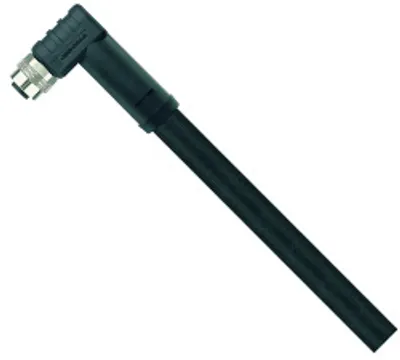
B&R VFC42040.000P
Accessories, flash controller
- MPN
- VFC42040.000P
Price and lead time confirmed within 1 business day
Request a Quote
- 12-month warranty (new) · 3-month (used/refurbished)
- 30-day returns, no restocking fee on unused parts
- Ships via



What is the B&R VFC42040.000P?
Machine vision flash controller, 4 channels each 20 A for external lighting, trigger inputs and outputs per channel, IP65/IP67 protection, POWERLINK interface with integrated 2-port hub
Specifications
Short description
| Accessories | Flash controller |
General information
| System requirements – Automation Studio | 4.12.0 |
| System requirements – Automation Runtime | 4.12.0 |
| System requirements – mapp Technology Package | 5.27 |
| System requirements – Hardware module upgrade | 1.0.0.0 |
| Certifications – CE | Yes |
| Certifications – CRA (Cyber Resilience Act) | In preparation |
| Certifications – UL | cTÜV SÜDus NRTL |
| Cooling | Passive |
| Diagnostics | Yes, using LED "Status" and software |
| Undervoltage detection | Yes |
| Reverse polarity protection | Yes |
Module power supply
| Connection | M12, 4-pin, L-coded, male |
| Nominal voltage | 24 VDC -15% / +20%, SELV/PELV |
| Max. input current | 8 A (note: Including the maximum output current of the digital outputs.) |
Interfaces
| Transfer – Physical layer | 100BASE-TX |
| Transfer – Half-duplex | Yes |
| Transfer – Full-duplex | No |
| Transfer – Autonegotiation | Yes |
| Transfer – Auto-MDI/MDIX | Yes |
| Quantity | 2 |
| Connection designation | IF1, IF2 |
| Fieldbus | POWERLINK |
| Type | POWERLINK (V2) managing or controlled node |
| Variant | M12, 8-pin, Y-coded, female (2-port hub, daisy-chain wiring possible) |
| Line length | Max. 30 m between 2 stations (segment length) |
| Transfer rate | 100 Mbit/s |
| Min. cycle time | 400 µs (note: The maximum cycle time should not exceed 10 ms.) |
Digital inputs
| Switching threshold – Low | <5 VDC |
| Switching threshold – High | >15 VDC |
| Electrical isolation – Channel - Channel | Yes |
| Electrical isolation – Channel - Power supply | Yes |
| Switching delay – Hardware | Min. 0 to max. 14 µs (note: Delay can be increased in trigger mode using software.) |
| Switching delay – Software | Configurable, minimum value 16 µs (note: Delay can be increased in trigger mode using software.) |
| Quantity | 4 |
| Connection designation | IF7, IF8, IF9, IF10 |
| Variant | M8, 4-pin, A-coded, female |
| Input characteristics per EN 61131-2 | Type 1 |
| Input voltage | 24 VDC -15% / +20% |
| Input current at 24 VDC | Typ. 3.7 mA |
| Input circuit | Sink/Source |
| Input resistance | Typ. 6.5 kΩ |
Digital outputs
| Switching delay – 0 → 1 | <1 µs |
| Switching delay – 1 → 0 | <1 µs |
| Protective measures – Short-circuit proof | Yes |
| Protective measures – Overtemperature shutdown | Yes |
| Quantity | 4 |
| Connection designation | IF7, IF8, IF9, IF10 |
| Variant | M8, 4-pin, A-coded, female |
| Nominal voltage | 24 VDC -15% / +20% |
| Output circuit | Push / Pull / Push-Pull |
| Leakage current when the output is switched off | Max. 200 µA |
| R DS(on) | Max. 0.1 Ω |
| Max. output current | 100 mA |
| Electrical isolation | No |
Output channels - Power output
| Max. output current in pulse operation – Per channel | 20 A per channel / 10 A per pin |
| Max. output current in pulse operation – All channels | 80 A |
| Max. output current in continuous operation – Per channel | 1 A |
| Max. output current in continuous operation – All channels | 2 A |
| Min. output current – Per channel | 250 mA |
| Max. output power in pulse operation – Per channel | 960 W (note: The maximum output voltage of 48 V is always used to calculate the output power, regardless of the actual output voltage.) |
| Max. output power in pulse operation – All channels | 3840 W (note: The maximum output voltage of 48 V is always used to calculate the output power, regardless of the actual output voltage.) |
| Max. output power in continuous operation – Per channel | 48 W (note: The maximum output voltage of 48 V is always used to calculate the output power, regardless of the actual output voltage.) |
| Max. output power in continuous operation – All channels | 96 W (note: The maximum output voltage of 48 V is always used to calculate the output power, regardless of the actual output voltage.) |
| Current rise time / Current fall time – At 20 A output current | <1 µs (note: Without taking line inductances into account.) |
| Max. pulse duration – Configurable | 2147 s (note: The maximum pulse duration may be reduced depending on the configuration (output power).) |
| Max. pulse duration – At full load, 1 channel | 4 ms |
| Max. pulse duration – At full load, all 4 channels simultaneously | 1 ms |
| Max. duty cycle – At 20 A output current | 4% (note: Depends on the output current setting.) |
| Max. duty cycle – At 250 mA output current | 100% (note: Depends on the output current setting.) |
| Max. pulse frequency – Per channel | 1000 pulses per 100 msMaximum pulse frequency"."> (note: With an even distribution, this corresponds to 10 kHz per channel. The limit is set to a duration of 100 ms. For shorter time intervals, frequencies higher than 10 kHz are therefore possible, provided this limit is observed. For additional information, see section) |
| Max. pulse frequency – All 4 channels | 2000 pulses per 100 msMaximum pulse frequency"."> (note: Sum of all 4 channels.) |
| Quantity | 4 |
| Connection designation | IF3, IF4, IF5, IF6 |
| Variant | M12, 5-pin, A-coded, female |
| Max. cable length | 20 m (note: Shorter maximum cable lengths may result when taking the voltage drop, required current rise and required fall time into account.) |
| Max. line inductance | 10 µH |
| Min. output voltage | 1 V (note: A minimum output power of 1.25 W must be maintained, which results in a higher minimum output voltage in the lower current range.) |
| Max. output voltage | 48 V |
| Current setting step size | 5 mA |
| Voltage setting step size | 50 mV |
| Voltage measurement resolution | 50 mV |
| Min. pulse duration | 1 µs |
Operating conditions
| Mounting orientation – Horizontal | Yes |
| Mounting orientation – Vertical | Yes |
| Mounting orientation – Face-up | Yes |
| Installation elevation above sea level – 0 to 2000 m | No limitations |
| Installation elevation above sea level – >2000 m | Reduction of ambient temperature by 0.5°C per 100 m |
| Installation elevation above sea level – Maximum | 5000 m |
| Pollution degree per EN 60664-1 | 2 |
| Overvoltage category per EN 60664-1 | II |
| Degree of protection per EN 60529 | IP67 |
Ambient conditions
| Temperature – Operation | -25 to 50°C |
| Temperature – Storage | -40 to 85°C |
| Temperature – Transport | -40 to 85°C |
| Relative humidity – Operation | 5 to 100%, condensing |
| Relative humidity – Storage | 5 to 95%, non-condensing |
| Relative humidity – Transport | 5 to 95%, non-condensing |
Mechanical properties
| Dimensions – Width | 270 mm |
| Dimensions – Length | 186 mm |
| Dimensions – Height | 65.1 mm |
| Material | Aluminum die casting |
| Weight | 2200 g |
Accessories
Optional accessories (8)
| VCA1L11.0200 | Cables — - Power attachment cable - 20.0 m - Connector: Angled |
| VCA1L11.0100 | Cables — - Power attachment cable - 10.0 m - Connector: Angled |
| VCA1L11.0050 | Cables — - Power attachment cable - 2.0 m - Connector: Angled |
| VCA1L11.0020 | Cables — - Power attachment cable - 2.0 m - Connector: Angled |
| VCA1L01.0200 | Cables — - Power attachment cable - 20.0 m - Connector: Straight |
| VCA1L01.0100 | Cables — - Power attachment cable - 10.0 m - Connector: Straight |
| VCA1L01.0050 | Cables — - Power attachment cable - 5.0 m - Connector: Straight |
| VCA1L01.0020 | Cables — - Power attachment cable - 2.0 m - Connector: Straight |
Downloads & documentation
Official documents from B&R, downloaded directly from the manufacturer.
Data sheets & manuals
CAD & dimension drawings
VFC42040.000P: frequently asked questions
When can VFC42040.000P be shipped?
VFC42040.000P is sourced on request — request a quote and we'll confirm the exact availability and shipping timeline for this specific unit.
Can I pick up VFC42040.000P in person?
Local pickup from our Groningen, Netherlands warehouse may be possible — contact us before ordering to check availability and arrange a collection time.
Is express delivery available?
Yes — mention it when you request a quote for VFC42040.000P and we'll include express shipping options in our reply.
My factory is down and I need this urgently — can you help?
For a critical breakdown, contact us directly at +31 (0)50-7110348 or sales@partnerplc.com — we can look into same-day courier or dedicated taxi/hotshot delivery for VFC42040.000P, subject to availability and destination.
More B&R parts
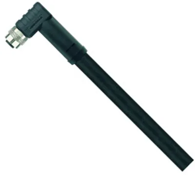
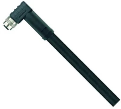
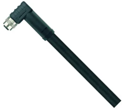
B&R VFC42040.000PPrice and lead time confirmed within 1 business day
Request a Quote