























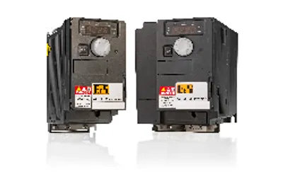
B&R 8I66T400037.00-000
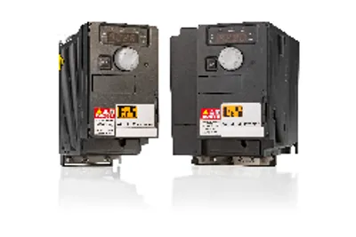
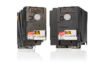
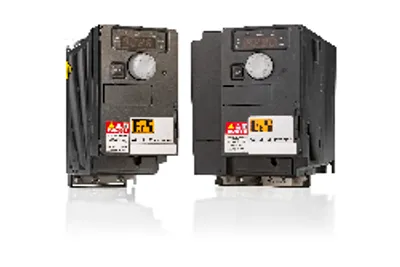
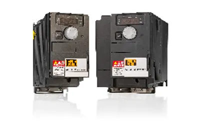
Base device for ACOPOSinverter P66 and P64new
- MPN
- 8I66T400037.00-000
Price and lead time confirmed within 1 business day
Request a Quote
- 1We check stock, condition and lead time
- 2You get a written quote by email
- 3Approve it and we ship — in-stock parts within 1 business day
- 12-month warranty (new) · 3-month (used/refurbished)
- 30-day returns, no restocking fee on unused parts
- 100% positive eBay feedback
- Ships via



What is the B&R 8I66T400037.00-000?
Base device for ACOPOSinverter P66 and P64new, 3 x 380 to 500 V, 0.37 kW, integrated EMC filter and brake chopper, shield plate included in delivery
Order number - ACOPOSinverter P66:
8I66T400037.0P-000: Inverter with POWERLINK communication card
8I66T400037.0X-000: Inverter with X2X Link communication card
8I66T400037.0C-000: Inverter with integrated CANopen interface
Order number - ACOPOSinverter P64new:
8I64T400037.0X-000: Inverter with X2X Link communication card
Specifications
General information
| Certifications – CE | Yes |
| Certifications – UKCA | Yes |
| Certifications – CRA (Cyber Resilience Act) | In preparation |
| Certifications – UL | cULus E225616; Power conversion equipment |
| Certifications – KC | Yes |
Motor power
| Specified on nameplate | 0.37 kW (0.5 HP) |
Mains connection
| Mains current – At 380 VAC | 1.8 A (note: Typical value for 4-pin motor and a max. clock frequency of 4 kHz, without mains choke for the max. assumed short circuit current (lsc).) |
| Mains current – At 500 VAC | 1.4 A (note: Typical value for 4-pin motor and a max. clock frequency of 4 kHz, without mains choke for the max. assumed short circuit current (lsc).) |
| Mains input voltage | 3x 380 VAC -15% to 500 VAC +10% |
| Frequency | 50 to 60 Hz ±5% |
| Apparent power (at 500 VAC) | 1.2 kVA |
| Max. assumed short-circuit current (Isc); (short-circuit current at connection point) | 5 kA (note: With mains choke max. Isc 65 kA for 380/500 V.) |
| Inrush current | Max. 10 A (note: Peak current when switching on for maximum voltage (240 V +10% or 500 V +10% or 600 V +10%)) |
| Power dissipation at nominal load and nominal clock frequency | 28 W |
| Integrated EMC filter | Yes (note: Inverter is provided with an integrated Category C2 EMC filter. This filter can be switched off.) |
Line-conducted and radiated emissions
| With integrated filter – Motor cable length per IEC/EN 61800-3 ; Cat. C2 environment 1 (public power network) | 10 m |
| With integrated filter – Motor cable length per IEC/EN 61800-3 ; Cat. C3 environment 2 (industrial power system) | 10 m |
| With add-on filter – Motor cable length per IEC/EN 61800-3 ; Cat. C1 environment 1 (public power network) | 20 m |
| With add-on filter – Motor cable length per IEC/EN 61800-3 ; Cat. C2 environment 1 (public power network) | 50 m |
| With add-on filter – Motor cable length per IEC/EN 61800-3 ; Cat. C3 environment 2 (industrial power system) | 150 m |
| With add-on filter | 8I0FT015.200-1 |
Motor connection
| Derating of continuous output current depending on ambient temperature – At nominal clock frequency (4 kHz) | No derating (up to 50°C) |
| Derating of continuous output current depending on ambient temperature – Other clock frequencies | The derating curves are included in the installation instructions, which can be downloaded from the website (www.br-automation.com). |
| Derating of continuous output current depending on installation elevation – Starting at 1000 m above sea level | 1%, per 100 m |
| Clock frequency – Min. | 2 kHz |
| Clock frequency – Max. | 16 kHz |
| Braking torque – With braking resistor | Up to 170% of the rated motor torque |
| Max. motor cable length – Shielded cable | 50 m |
| Max. motor cable length – Non-shielded cable | 100 m |
| Motor control profiles – Induction motor | Sensorless vector control: ; 1. Voltage controlled with constant torque → standard mode; 2. Voltage controlled with variable torque → energy saving mode e.g. for fans and pumps; Sensorless slip control: ; 1. With V/f characteristic curve for constant torque → standard mode; 2. With V/f characteristic curve for constant torque (up to 6 f-ranges) → Custom mode for special applications; 3. With V/f characteristic curve for quadratically increasing torque → Energy-saving mode, e.g. for fans and pumps |
| Motor control profiles – Synchronous motor | Sensorless vector control: ; 1. Voltage controlled with constant torque → standard mode |
| Nominal output current | 1.5 A (note: These values apply at a nominal clock frequency of 4 kHz during continuous operation. The clock frequency can be set from 2 to 16 kHz. Above 4 kHz, reduce the nominal drive current. The nominal motor current is not permitted to exceed this value.) |
| Max. transient current for 60 s | 2.3 A (note: The inverter is designed to operate for a maximum of 60 seconds at 150% nominal current.) |
| Output frequency range | 0.1 to 599 Hz |
| Nominal clock frequency | 4 kHz |
| Main protective functions of inverter | Thermal protection against power stage overheating; Protection against short circuits between motor phases, overcurrent between output phases and ground, overvoltages on the DC bus, exceeding the speed limit. ; Safety function for: Overvoltage and undervoltage of the mains supply, mains phase failure with 3-phase power supply |
Brake chopper
| Integrated dynamic brake transistors | Yes |
| Min. resistance value (external) | 80 Ω |
24 VDC power supply
| Input voltage | 24 VDC (-15%/+20%) |
| Current | Max. 1.1 A |
Available internal power supplies
| Output voltage 24 VDC – Max. output current at 24 VDC | 100 mA |
| Output voltage 10 VDC – Max. output current at 10 VDC | 10 mA |
| Output voltage 24 VDC | 24 VDC (-15%/+20%) |
| Output voltage 10 VDC | 10 VDC (-0%/+10%) |
Interfaces
| POWERLINK – Type | Type 3Communication / POWERLINK / General information / Hardware - CN" in Automation Help."> (note: For additional information, see section) |
Digital inputs
| Electrical isolation – Input - ACOPOSinverter | Yes |
| Electrical isolation – Input - Input | No |
| Digital input 5 – Max. input frequency | 20 kHz |
| Quantity | 6 (note: 1 logic input can be programmed as a 20 kbps pulse input. 1 logic input is configurable as an input for a PTC sensor using a switch (SW2). Trigger resistance 3 kΩ, reset value 1.8 kΩ, short-circuit proof <50 Ω) |
| Nominal voltage | 24 VDC (max. 30 VDC) |
| Input circuit | Source or sink |
| Switching threshold | Sink: >19 V (position 0), <13 V (position 1); Source: <5 V (position 0), >11 V (position 1) |
| Sampling time | 8 ms ±0.7 ms |
Safe input - STO (Safe Torque Off)
| Input impedance – Current consumption | 16 mA |
| Electrical isolation – Input - ACOPOSinverter | Yes |
| Electrical isolation – Input - Input | No |
| Quantity | 1 |
| Nominal voltage | 24 VDC (max. 30 VDC) |
| Input impedance | 1.5 kΩ |
Analog inputs
| Electrical isolation – Input - Input | No |
| Electrical isolation – Input - ACOPOSinverter | Yes |
| Input – Voltage | AI1: 0 to 10 VDC; AI2: 0 ±10 VDC, max. 30 VDC |
| Input – Current | 0 to 20 mA (or 4 to 20 mA) |
| Input impedance – Voltage | 30 kΩ |
| Input impedance – Current | 250 Ω |
| Quantity | 3 |
| Nonlinearity | ±0.2%, max. ±0.5% |
| Basic accuracy | At 25°C: ±0.5%; At -10 to 60°C: ±0.7% |
| Resolution | 10-bit |
| Sampling time | 2 ms |
Digital outputs
| Quantity | 1 |
| Nominal voltage | 24 VDC -15%/+20% |
| Max. voltage | 30 VDC |
| Output circuit | Source or sink |
| Sampling time | 2 ms |
| Max. current | 100 mA |
Relay outputs
| Execution – Relay 1 | 1 changeover contact |
| Execution – Relay 2 | 1 normally open contact |
| Electrical isolation – Output - ACOPOSinverter | Yes |
| Electrical isolation – Output - Output | No |
| Quantity | 2 |
| Nominal voltage | 30 VDC / 250 VAC |
| Switching current range | Min. switching current: 5 mA at 24 VDC; Max. switching current:; R1 at cos φ = 1: 3 A at 250 VAC / 4 A at 30 VDC; R2 at cos φ = 1: 5 A; R1 and R2 at cos φ = 0.4: 2 A |
| Response time (max.) | 2 ms |
Analog outputs
| Electrical isolation – Output - ACOPOSinverter | Yes |
| Electrical isolation – Output - Output | No |
| Max. load impedance – Voltage | 470 Ω |
| Max. load impedance – Current | 800 Ω |
| Quantity | 1 |
| Output | 0 to 10 V or 0 to 20 mA |
| Nonlinearity | ±0.3% |
| Basic accuracy | At 25°C: ±1%; At -10 to 60°C: ±2% |
| Update time | 2 ms |
| Resolution | 10-bit |
Electrical properties
| Energy efficiency (IE classification) – Power dissipation relative to continuous apparent power | IE2 (10, 25): 1.8% (3x 380 VAC), 1.4% (3x 500 VAC); IE2 (50, 25): 1.7% (3x 380 VAC), 1.3% (3x 500 VAC); IE2 (10, 50): 1.9% (3x 380 VAC), 1.5% (3x 500 VAC); IE2 (50, 50): 1.7% (3x 380 VAC), 1.5% (3x 500 VAC); IE2 (90, 50): 1.8% (3x 380 VAC), 1.5% (3x 500 VAC); IE2 (10, 100): 2.2% (3x 380 VAC), 2% (3x 500 VAC); IE2 (50, 100): 2.1% (3x 380 VAC), 1.9% (3x 500 VAC); IE2 (90, 100): 2.3% (3x 380 VAC), 1.9% (3x 500 VAC) |
| Energy efficiency (IE classification) – Nominal losses in standby mode | 7 W (3x 380 VAC), 9 W (3x 500 VAC) |
Operating conditions
| Degree of protection per EN 61800-5-1 | IP20 |
| Relative humidity per IEC 60068-2-3 | 5 to 95%, non-condensing; No dripping water |
| Maximum installation elevation | ≤1000 m without derating; 1000 to 3000 m with Derating (note: Over 1000 m, load reduced by 1% per 100 m.) |
| Max. pollution degree per IEC/EN 61800-5-1 | 2 (non-conductive pollution) |
| Ambient conditions per IEC 60721-3-3 | Class 3C3 and 3S2 |
| Operating position | Vertical mounting orientation ±10° |
Ambient conditions
| Temperature – Operation | -10 to 50°C without derating; 50 to 60°C with derating |
| Temperature – Storage | -25 to 70°C |
| Max. vibration resistance | 1 g n 13 to 200 Hz EN/IEC 60068-2-6; 1.5 mm peak to peak 2 to 13 Hz EN/IEC 60068-2-6 |
Mechanical properties
| Dimensions – Width | 105 mm |
| Dimensions – Height | 189 mm |
| Dimensions – Height without shield plate | 143 mm |
| Dimensions – Depth | 158 mm |
| Weight | 1.2 kg |
No matching specifications
Accessories
Optional accessories (21)
| 8I0XE066.402-1 | Optional EMC kit — ACPi P66 EMC kit for size B 1ph. 200…240 VAC: Power output class: 1.1 -2.2 kW 3ph. 200…240 VAC: Power output class: 1.1 - 2.2 kW 3ph. 380…5… |
| 8I0XD304.310-1 | Cable and adapters — RJ45 cable, 10 m, for remote use of the display for the ACOPOSinverter. |
| 8I0XD304.305-1 | Cable and adapters — RJ45 cable, 5 m, for remote use of the display for the ACOPOSinverter. |
| 8I0XD304.303-1 | Cable and adapters — RJ45 cable, 3 m, for remote use of the display for the ACOPOSinverter. |
| 8I0XD304.301-1 | Cable and adapters — RJ45 cable, 1 m, for remote use of the display for the ACOPOSinverter. |
| 8I0XC001.003-1 | Cable and adapters — USB adapter cable, USB to Modbus, for ACOPOSinverter. |
| 8I0XT001.000-1 | Cable and adapters (CANopen) — Terminating resistor 120 Ω, RJ45, for integrated CANopen interface of the ACOPOSinverter. |
| 8I0CA001.000-1 | Cable and adapters (CANopen) — Y-cable, RJ45, daisy chain connection ≤0.3 m, for integrated CANopen interface of the ACOPOSinverter. |
| 8I0XD305.300-1 | Graphic display — Female to female adapter, RJ45, for graphics display of the ACOPOSinverter. |
| 8I0XD303.300-1 | Graphic display — Front cover for installation kit, IP65 protection, for graphic display of the ACOPOSinverter. |
| 8I0XD302.300-1 | Graphic display — Installation kit, IP54 protection, for graphic display of the ACOPOSinverter. |
| 8I0XD301.300-1 | Graphic display — Graphics display for ACOPOSinverter, 240 x 160 pixels, 8 lines, backlight, function keys, navigation key, IP54 protection. |
| 8I0FT015.200-2 | Optional EMC filters — ACPi additional EMC input filter 3-phase 15 A supply voltage 3-phase: 200...240 V 50/60 Hz |
| 8I0BR100.000-1 | Optional braking resistors — Braking resistor ohmic value: 100 Ω continuous braking power: 0.05 kW degree of protection (IP): IP20 |
| 8I0CT004.000-1 | Optional line chokes — Mains choke 3-phase, 4 A, 50/60 for ACOPOSinverter |
| 8TB2108.2210-00 | Terminal blocks — 8-pin push-in terminal block, 1-row, pitch: 5.08 mm, label 1: Numbered consecutively |
| 8TB2108.2010-00 | Terminal blocks — 8-pin screw clamp terminal block, 1-row, pitch: 5.08 mm, label 1: Numbered consecutively |
| 8TB2104.2210-00 | Terminal blocks — 4-pin push-in terminal block, 1-row, pitch: 5.08 mm, label 1: Numbered consecutively |
| 8TB2104.2010-00 | Terminal blocks — 4-pin screw clamp terminal block, 1-row, pitch: 5.08 mm, label 1: Numbered consecutively |
| X67CA0X99.5000 | X2X Link Cable — Cable for custom assembly, 500 m |
| X67CA0X99.1000 | X2X Link Cable — Cable for custom assembly, 100 m |
Downloads & documentation
Official documents from B&R, downloaded directly from the manufacturer.
Data sheets & manuals
CAD & dimension drawings
8I66T400037.00-000: frequently asked questions
When can 8I66T400037.00-000 be shipped?
8I66T400037.00-000 is sourced on request — request a quote and we'll confirm the exact availability and shipping timeline for this specific unit.
Can I pick up 8I66T400037.00-000 in person?
Local pickup from our Groningen, Netherlands warehouse may be possible — contact us before ordering to check availability and arrange a collection time.
Is express delivery available?
Yes — mention it when you request a quote for 8I66T400037.00-000 and we'll include express shipping options in our reply.
My factory is down and I need this urgently — can you help?
For a critical breakdown, contact us directly at +31 (0)50-7110348 or sales@partnerplc.com — we can look into same-day courier or dedicated taxi/hotshot delivery for 8I66T400037.00-000, subject to availability and destination.
More B&R parts
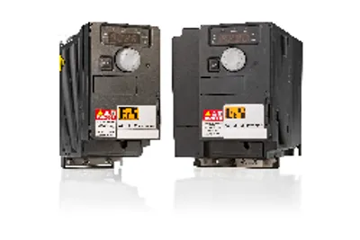
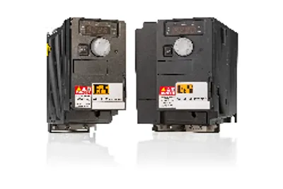
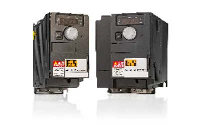
B&R 8I66T400037.00-000Price and lead time confirmed within 1 business day
Request a Quote