























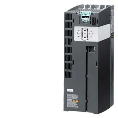
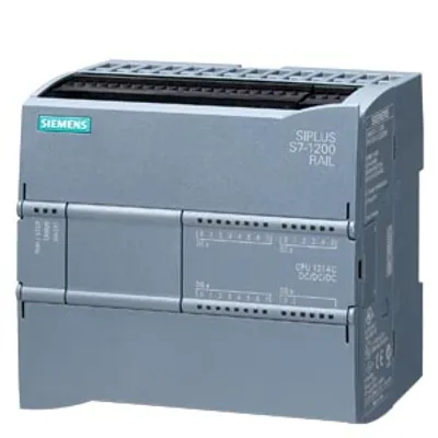
Siemens 6AG1210-1PE31-2UL0
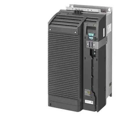
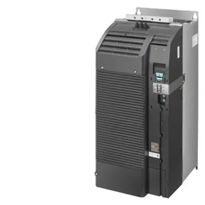
SIPLUS G120 PM240-2 IP20-FSF-U-400V 75 kW based on 6SL3210-1PE31-5UL0 with conformal coating, -20…+50 °C
- MPN
- 6AG1210-1PE31-2UL0
- Category
- SIPLUS Power Modules
Price and lead time confirmed within 1 business day
Request a Quote
- 12-month warranty (new) · 3-month (used/refurbished)
- 30-day returns, no restocking fee on unused parts
- Ships via



- 100% positive eBay feedback
What is the Siemens 6AG1210-1PE31-2UL0?
SIPLUS G120 PM240-2 IP20-FSF-U-400V 75 kW based on 6SL3210-1PE31-5UL0 with conformal coating, -20…+50 °C, unfiltered with integrated braking chopper 380-480 V 3 AC +10/-20% 47-63 Hz power high overload: 55 kW at 200% 3 s,150% 57 s,100% 240 s power low overload: 75 kW at 150% 3 s,110% 57 s,100% 240 s 708x 305x 357 (HxWxD), FSF design, degree of protection IP20 without CU and operating unit released as of CU FW version V4.7 HF8
Specifications
General information
| Product type designation | PM240-2 |
| Product version | FSF 75 kW |
| Design of the converter | FSF |
| based on | 6SL3210-1PE31-5UL0 |
| Protection function — Undervoltage protection | Yes |
| Protection function — Overvoltage protection | Yes |
| Protection function — Overload protection | Yes |
| Protection function — Ground-fault protection | Yes |
| Protection function — short-circuit protection | Yes |
| Protection function — Stall protection | Yes |
| Protection function — With blocked rotor | Yes |
| Protection function — Temperature monitor for motor | Yes |
| Protection function — Temperature monitor for converter | Yes |
| Protection function — Parameter locking | Yes |
Input voltage
| Type of input voltage | AC |
| Mains filter — present | No |
Input current
| Input current with low overload | 140 A |
| Input current with high overload | 117 A |
Output voltage
| Output voltage in relation to input voltage, min. | 0 % |
| Output voltage in relation to input voltage, max. | 95 % |
| Pulse frequency | 4 kHz |
Output current
| Output current, max. | 220 A |
| Output current without overload | 145 A |
| Output current with low overload | 145 A |
| Output current with high overload | 110 A |
Power loss
| Power loss, max. | 1.776 kW |
| Power loss of the CDM in standby mode | 48.1 W |
| Power loss of the CDM at the operating point (0/25) | 586.4 W |
| Power loss of the CDM at the operating point (0/50) | 791.2 W |
| Power loss of the CDM at the operating point (0/100) | 1 395.3 W |
| Power loss of the CDM at the operating point (50/25) | 620.9 W |
| Power loss of the CDM at the operating point (50/50) | 870.5 W |
| Power loss of the CDM at the operating point (50/100) | 1 606.3 W |
| Power loss of the CDM at the operating point (90/50) | 984.7 W |
| Power loss of the CDM at the operating point (90/100) | 1 953.8 W |
| Relative power loss of the CDM at the operating point (0/25) | 0.58 % |
| Relative power loss of the CDM at the operating point (0/50) | 0.79 % |
| Relative power loss of the CDM at the operating point (0/100) | 1.39 % |
| Relative power loss of the CDM at the operating point (50/25) | 0.62 % |
| Relative power loss of the CDM at the operating point (50/50) | 0.87 % |
| Relative power loss of the CDM at the operating point (50/100) | 1.6 % |
| Relative power loss of the CDM at the operating point (90/50) | 0.98 % |
| Relative power loss of the CDM at the operating point (90/100) | 1.94 % |
| Ratio of converter losses / reference converter losses at the operating point (90/100) | 0.42 |
| IE class of the CDM | IE2 |
Power electronics
| emitted active power with low overload | 75 kW |
| emitted active power with high overload | 55 kW |
| active power output with low overload [hp] | 100 hp |
| active power output with high overload [hp] | 75 hp |
| apparent power output | 100.46 kVA |
| Efficiency | 0.98 |
| Type of duty cycle duration with low overload | 1.1x rated output current (i.e. 110 % overload) for 57 s with a cycle time of 300 s; 1.5x rated output current (i.e. 150 % overload) for 3 s with a cycle time of 300 s |
| Type of duty cycle duration with high overload | 1.5x output current rating (i.e. 150 % overload) for 57 s with a cycle time of 300 s; 2x output current rating (i.e. 200 % overload) for 3 s with a cycle time of 300 s |
| Cooling method | Internal air cooling |
| Cooling air flow | 0.153 m³/s |
| Short-time withstand current (SCCR) of the entire control cabinet in accordance with UL 508A | 65 kA |
Isolation
| Degree of pollution | 2 according to EN 61800-5-1 |
Degree and class of protection
| IP degree of protection | IP20 |
| Equipment protection class according to EN 61800-5-1 | Class I (with protective bonding circuit) and Class III (PELV) |
| Touch protection according to EN 61800-5-1 | Assuming use as prescribed |
Standards, approvals, certificates
| Certificate of suitability | CE / TÜV |
| Standard for EMC according to EN 61800-3 | the EMC product standard EN 61800-3 does not apply directly to a frequency inverter but to a PDS (Power Drive System), which comprises the complete circuitry, motor and cables in addition to the inverter |
Ambient conditions
| Ambient temperature during operation — min. | -20 °C; = Tmin |
| Ambient temperature during operation — max. | 50 °C; = Tmax |
| Ambient temperature during storage/transportation — Storage, min. | -25 °C |
| Ambient temperature during storage/transportation — Storage, max. | 55 °C |
| Ambient temperature during storage/transportation — Storage, min. [°F] | -13 °F |
| Ambient temperature during storage/transportation — Storage, max. [°F] | 131 °F; Class 1K3 acc. to EN 60721-3-1 |
| Ambient temperature during storage/transportation — Transportation, min. | -40 °C |
| Ambient temperature during storage/transportation — Transportation, max. | 70 °C |
| Ambient temperature during storage/transportation — Transport, min. [°F] | -40 °F |
| Ambient temperature during storage/transportation — Transport, max. [°F] | 158 °F; Class 2K3 according to EN 60721-3-2 |
| Altitude during operation relating to sea level — Installation altitude above sea level without derating, max. | 1 000 m |
| Relative humidity — Operation, max. | 98 % |
| Relative humidity — Condensation permissible | No |
| Vibrations — Vibration frequency with constant acceleration during operation according to EN 60068-2-6, min. | 10 Hz |
| Vibrations — Vibration frequency with constant acceleration during operation according to EN 60068-2-6, max. | 200 Hz; Constant acceleration = 9.81 m/s² (1 g) |
| Vibrations — Vibration frequency with constant deflection during operation according to EN 60068-2-6, min. | 13 Hz |
| Vibrations — Vibration frequency with constant deflection during operation according to EN 60068-2-6, max. | 58 Hz; Constant deflection 0.075 mm |
| Vibrations — Oscillation frequency during transport in accordance with EN 60721-3-2 | Class 2M3 |
| Shock testing — Shock load during operation | (15x g)/11 ms |
| Shock testing — Shock acceleration during operation according to EN 60068-2-27 | 147 m/s² |
| Shock testing — Shock acceleration during transport according to EN 60721-3-2 | Class 2M3 |
| Resistance — Use in stationary industrial systems — to biologically active substances according to EN 60721-3-3 | Yes; Class 3B2 mold, fungus and dry rot spores (with the exception of fauna); Class 3B3 on request |
| Resistance — Use in stationary industrial systems — to chemically active substances according to EN 60721-3-3 | Yes; Class 3C4 (RH < 75 %) incl. salt spray acc. to EN 60068-2-52 (severity degree 3); * |
| Resistance — Use in stationary industrial systems — to mechanically active substances according to EN 60721-3-3 | No |
| Resistance — Usage in industrial process technology — Against chemically active substances acc. to EN 60654-4 | Yes; Class 3 (excluding trichlorethylene) |
| Resistance — Usage in industrial process technology — Environmental conditions for process, measuring and control systems acc. to ANSI/ISA-71.04 | Yes; Level GX group A/B (excluding trichlorethylene; harmful gas concentrations up to the limits of EN 60721-3-3 class 3C4 permissible); level LC3 (salt spray) and level LB3 (oil) |
| Resistance — Remark — Note regarding classification of environmental conditions acc. to EN 60721, EN 60654-4 and ANSI/ISA-71.04 | * The supplied plug covers must remain in place over the unused interfaces during operation! |
| Conformal coating — Coatings for printed circuit board assemblies acc. to EN 61086 | Yes; Class 2 for high reliability |
| Conformal coating — Military testing according to MIL-I-46058C, Amendment 7 | Yes; Discoloration of coating possible during service life |
| Conformal coating — Qualification and Performance of Electrical Insulating Compound for Printed Board Assemblies according to IPC-CC-830A | Yes; Conformal coating, Class A |
Cables
| Cable length for motor, shielded, max. | 300 m |
| Cable length for braking resistor, max. | 10 m |
Connection method
| Design of electrical connection of motor | M10 screw stud |
| Design of electrical connection of motor — connectable cable cross-section for motor supply line, min. | 35 mm² |
| Design of electrical connection of motor — connectable cable cross-section for motor supply line, max. | 120 mm² |
| Design of electrical connection of motor — Connectable conductor cross-section for AWG cables, min. | 2 |
| Type of electrical connection for mains supply line | M10 screw stud |
| Type of electrical connection for mains supply line — connectable cable cross-section for mains supply line, min. | 35 mm² |
| Type of electrical connection for mains supply line — connectable cable cross-section for mains supply line, max. | 120 mm² |
| Type of electrical connection for mains supply line — Connectable conductor cross-section for AWG cables, min. | 2 |
| Type of electrical connection for supply cable to braking resistor | Screw terminals |
| Type of electrical connection for supply cable to braking resistor — Connectable cable cross-section for supply cable to braking resistor, min. | 25 mm² |
| Type of electrical connection for supply cable to braking resistor — Connectable cable cross-section for supply cable to braking resistor, max. | 70 mm² |
| Type of electrical connection for supply cable to braking resistor — Connectable conductor cross-section for AWG cables, min. | 4 |
| Design of electrical connection for the PE conductor | M10 screw stud |
Dimensions
| Width | 305 mm |
| Height | 708 mm |
| Depth | 357 mm |
Weights
| Weight (without packaging) | 57 kg |
Other
| Sound pressure level (1 m), max. | 67.7 dB |
| Brake design | DC braking, compound braking, resistance braking with integrated brake chopper (for size FSGX optional) |
Downloads & documentation
Official documents from Siemens, downloaded directly from the manufacturer.
Data sheets & manuals
6AG1210-1PE31-2UL0: frequently asked questions
When can 6AG1210-1PE31-2UL0 be shipped?
6AG1210-1PE31-2UL0 is sourced on request — request a quote and we'll confirm the exact availability and shipping timeline for this specific unit.
Can I pick up 6AG1210-1PE31-2UL0 in person?
Local pickup from our Groningen, Netherlands warehouse may be possible — contact us before ordering to check availability and arrange a collection time.
Is express delivery available?
Yes — mention it when you request a quote for 6AG1210-1PE31-2UL0 and we'll include express shipping options in our reply.
My factory is down and I need this urgently — can you help?
For a critical breakdown, contact us directly at +31 (0)50-7110348 or sales@partnerplc.com — we can look into same-day courier or dedicated taxi/hotshot delivery for 6AG1210-1PE31-2UL0, subject to availability and destination.
More Siemens parts
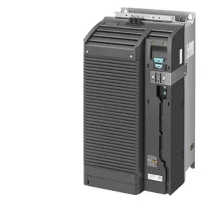
Siemens 6AG1210-1PE31-2UL0Price and lead time confirmed within 1 business day
Request a Quote