


Pepperl Fuchs KFD2-UT2-2
Request a Quote



Quick facts
| Availability | Confirmed on request |
| Category | K-System (DIN Rail Mounting, Highly Functional) |
| Lifecycle | active |
| Warranty | 12-month (new) · 3-month (used/refurbished) |
Shipping & availability
When can KFD2-UT2-2 be shipped?
KFD2-UT2-2 is sourced on request — request a quote and we'll confirm the exact availability and shipping timeline for this specific unit.
Can I pick up KFD2-UT2-2 in person?
Local pickup from our Groningen, Netherlands warehouse may be possible — contact us before ordering to check availability and arrange a collection time.
Is express delivery available?
Yes — mention it when you request a quote for KFD2-UT2-2 and we'll include express shipping options in our reply.
My factory is down and I need this urgently — can you help?
For a critical breakdown, contact us directly at +31 (0)50-7110348 or sales@partnerplc.com — we can look into same-day courier or dedicated taxi/hotshot delivery for KFD2-UT2-2, subject to availability and destination.
Universal Temperature Converter. 2-channel signal conditioner, 24 V DC supply (Power Rail), Thermocouple, RTD, potentiometer or voltage input, Usable as signal splitter (1 input and 2 outputs), Current output 0/4 mA ... 20 mA, Sink or source mode, Configurable by PACTware, Line fault (LFD) and sensor burnout detection, Up to SIL 2 acc. to IEC/EN 61508 / IEC/EN 61511, Housing width: 20 mm, Number of channels: 2-channel, Safety Integrity Level (SIL): SIL 2, Rated voltage: 20 ... 30 V DC. Signal type: Analog input. Safety Integrity Level (SIL): SIL 2. Connection: terminals 14+, 15- or power feed module/Power Rail. Rated voltage: 20 ... 30 V DC. Ripple: within the supply tolerance. Power dissipation: ≤ 1.53 W. Power consumption: max. 1.53 W. Programming interface: programming socket. Connection side: field side. Connection: terminals 1, 2, 3; 4, 5, 6. RTD: type Pt10, Pt50, Pt100, Pt500, Pt1000 (EN 60751: 1995)type Pt10GOST, Pt50GOST, Pt100GOST, Pt500GOST, Pt1000GOST (6651-94)type Cu10, Cu50, Cu100 (P50353-92)type Ni100 (DIN 43760). Measuring currentapprox. 200 µA with RTDTypes of measuring2-, 3-wire connectionLead resistancemax. 50 Ω per lineMeasurement loop monitoringsensor breakage, sensor short-circuit: . Measuring current: approx. 200 µA with RTD. Types of measuring: 2-, 3-wire connection. Lead resistance: max. 50 Ω per line. Measurement loop monitoring: sensor breakage, sensor short-circuit. Thermocouples: type B, E, J, K, N, R, S, T (IEC 584-1: 1995)type L (DIN 43710: 1985)type TXK, TXKH, TXA (P8.585-2001). Cold junction compensationexternal and internalMeasurement loop monitoringsensor breakage: . Cold junction compensation: external and internal. Measurement loop monitoring: sensor breakage. Potentiometer: 0 ... 20 kΩ (2-wire connection), 0.8 ... 20 kΩ (3-wire connection). Voltage: selectable within the range -100 ... 100 mV. Input resistance: ≥ 1 MΩ (-100 ... 100 mV). Connection side: control side. Connection: output I: terminal 7: source (-), sink (+), terminal 8: source (+), terminal 9: sink(-) output II: terminal 10: source (-), sink (+), terminal 11: source (+), terminal 12: sink(-). Output I, II: Analog current output. Current range0 ... 20 mA or 4 ... 20 mAFault signaldownscale 0 or 2 mA, upscale 21.5 mA (acc. NAMUR NE43)Sourceload 0 ... 550 Ω open-circuit voltage ≤ 18 VSinkVoltage across terminals 5 ... 30 V. If the current is supplied from a source > 16.5 V,series resistance of ≥ (V - 16.5)/0.0215 Ω is needed, where V is the source voltage.The maximum value of the resistance is (V - 5)/0.0215 Ω.: . Current range: 0 ... 20 mA or 4 ... 20 mA. Fault signal: downscale 0 or 2 mA, upscale 21.5 mA (acc. NAMUR NE43). Source: load 0 ... 550 Ω open-circuit voltage ≤ 18 V. Sink: Voltage across terminals 5 ... 30 V. If the current is supplied from a source > 16.5 V,series resistance of ≥ (V - 16.5)/0.0215 Ω is needed, where V is the source voltage.The maximum value of the resistance is (V - 5)/0.0215 Ω.. Deviation: . After calibrationPt100: ± (0.06 % of measurement value in K + 0.1 % of span + 0.1 K (4-wire connection)) thermocouple: ± (0.05 % of measurement value in °C + 0.1 % of span + 1 K (1.2 K for types R and S)) , includes ± 0.8 K fault of the cold junction compensation (CJC) mV: ± (50 µV + 0.1 % of span)potentiometer: ± (0.05 % of full scale + 0.1 % of span, (excludes faults due to lead resistance))Influence of ambient temperaturePt100: ± (0.0015 % of measurement value in K + 0.006 % of span)/K ΔTamb*)thermocouple: ± (0.02 K + 0.005 % of measurement value in °C + 0.006 % of span)/K ΔTamb*)), influence of cold junction compensation (CJC) includedmV: ± (0.01 % of measurement value + 0.006 % of span)/K ΔTamb*)potentiometer: ± 0.006 % of span/K ΔTamb*) *) ΔTamb = ambient temperature change referenced to 23 °C (296 K)Influence of supply voltage< 0.01 % of spanInfluence of load≤ 0.001 % of output value per 100 Ω: . After calibration: Pt100: ± (0.06 % of measurement value in K + 0.1 % of span + 0.1 K (4-wire connection)) thermocouple: ± (0.05 % of measurement value in °C + 0.1 % of span + 1 K (1.2 K for types R and S)) , includes ± 0.8 K fault of the cold junction compensation (CJC) mV: ± (50 µV + 0.1 % of span)potentiometer: ± (0.05 % of full scale + 0.1 % of span, (excludes faults due to lead resistance)). Influence of ambient temperature: Pt100: ± (0.0015 % of measurement value in K + 0.006 % of span)/K ΔTamb*)thermocouple: ± (0.02 K + 0.005 % of measurement value in °C + 0.006 % of span)/K ΔTamb*)), influence of cold junction compensation (CJC) includedmV: ± (0.01 % of measurement value + 0.006 % of span)/K ΔTamb*)potentiometer: ± 0.006 % of span/K ΔTamb*) *) ΔTamb = ambient temperature change referenced to 23 °C (296 K). Influence of supply voltage: < 0.01 % of span. Influence of load: ≤ 0.001 % of output value per 100 Ω. Reaction time: worst case value (sensor breakage and/or sensor short circuit detection enabled)mV: 1.2 s, thermocouples with CJC: 1.4 s, thermocouples with fixed ref. temp: 1.4 s, 3- or 4-wire RTD: 1.1 s, 2-wire RTD: 920 ms, Potentiometer: 3-wire connection 2.8 s, 2-wire connection 2.25 s. Input/Other circuits: basic insulation according to IEC 61010-1, rated insulation voltage 300 Veff. Output/supply, programming input: functional insulation, rated insulation voltage 50 V AC There is no electrical isolation between the programming input and the supply.The programming cable provides galvanic isolation so that ground loops are avoided.. Display elements: LEDs. Configuration: via PACTware. Labeling: space for labeling at the front. Electromagnetic compatibility: . Directive 2014/30/EUEN 61326-1:2013 (industrial locations): . Directive 2014/30/EU: EN 61326-1:2013 (industrial locations). Electromagnetic compatibility: NE 21:2006. Degree of protection: IEC 60529:2001. Ambient temperature: -20 ... 60 °C (-4 ... 140 °F). Degree of protection: IP20. Connection: screw terminals. Mass: approx. 130 g. Dimensions: 20 x 119 x 115 mm (0.8 x 4.7 x 4.5 inch) (W x H x D) , housing type B2. Height119 mmWidth20 mmDepth115 mm: . Height: 119 mm. Width: 20 mm. Depth: 115 mm. Mounting: on 35 mm DIN mounting rail acc. to EN 60715:2001. Supplementary information: Observe the certificates, declarations of conformity, instruction manuals, and manuals where applicable. For information see www.pepperl-fuchs.com.
Specifications
General specifications
| Signal type | Analog input |
Functional safety related parameters
| Safety Integrity Level (SIL) | SIL 2 |
Supply
| Connection | terminals 14+, 15- or power feed module/Power Rail |
| Rated voltage | 20 ... 30 V DC Ur |
| Ripple | within the supply tolerance |
| Power dissipation | ≤ 1.53 W |
| Power consumption | max. 1.53 W |
Interface
| Programming interface | programming socket |
Input
| Connection side | field side |
| Connection | terminals 1, 2, 3; 4, 5, 6 |
| RTD | type Pt10, Pt50, Pt100, Pt500, Pt1000 (EN 60751: 1995)type Pt10GOST, Pt50GOST, Pt100GOST, Pt500GOST, Pt1000GOST (6651-94)type Cu10, Cu50, Cu100 (P50353-92)type Ni100 (DIN 43760) |
| Measuring currentapprox. 200 µA with RTDTypes of measuring2-, 3-wire connectionLead resistancemax. 50 Ω per lineMeasurement loop monitoringsensor breakage, sensor short-circuit | Measuring current |
| Measuring current | approx. 200 µA with RTD |
| Types of measuring | 2-, 3-wire connection |
| Lead resistance | max. 50 Ω per line |
| Measurement loop monitoring | sensor breakage, sensor short-circuit |
| Thermocouples | type B, E, J, K, N, R, S, T (IEC 584-1: 1995)type L (DIN 43710: 1985)type TXK, TXKH, TXA (P8.585-2001) |
| Cold junction compensationexternal and internalMeasurement loop monitoringsensor breakage | Cold junction compensation |
| Cold junction compensation | external and internal |
| Measurement loop monitoring | sensor breakage |
| Potentiometer | 0 ... 20 kΩ (2-wire connection), 0.8 ... 20 kΩ (3-wire connection) |
| Voltage | selectable within the range -100 ... 100 mV |
| Input resistance | ≥ 1 MΩ (-100 ... 100 mV) |
Output
| Connection side | control side |
| Connection | output I: terminal 7: source (-), sink (+), terminal 8: source (+), terminal 9: sink(-) output II: terminal 10: source (-), sink (+), terminal 11: source (+), terminal 12: sink(-) |
| Output I, II | Analog current output |
| Current range0 ... 20 mA or 4 ... 20 mAFault signaldownscale 0 or 2 mA, upscale 21.5 mA (acc. NAMUR NE43)Sourceload 0 ... 550 Ω open-circuit voltage ≤ 18 VSinkVoltage across terminals 5 ... 30 V. If the current is supplied from a source > 16.5 V,series resistance of ≥ (V - 16.5)/0.0215 Ω is needed, where V is the source voltage.The maximum value of the resistance is (V - 5)/0.0215 Ω. | Current range |
| Current range | 0 ... 20 mA or 4 ... 20 mA |
| Fault signal | downscale 0 or 2 mA, upscale 21.5 mA (acc. NAMUR NE43) |
| Source | load 0 ... 550 Ω open-circuit voltage ≤ 18 V |
| Sink | Voltage across terminals 5 ... 30 V. If the current is supplied from a source > 16.5 V,series resistance of ≥ (V - 16.5)/0.0215 Ω is needed, where V is the source voltage.The maximum value of the resistance is (V - 5)/0.0215 Ω. |
Transfer characteristics
| Deviation | |
| After calibrationPt100: ± (0.06 % of measurement value in K + 0.1 % of span + 0.1 K (4-wire connection)) thermocouple: ± (0.05 % of measurement value in °C + 0.1 % of span + 1 K (1.2 K for types R and S)) , includes ± 0.8 K fault of the cold junction compensation (CJC) mV: ± (50 µV + 0.1 % of span)potentiometer: ± (0.05 % of full scale + 0.1 % of span, (excludes faults due to lead resistance))Influence of ambient temperaturePt100: ± (0.0015 % of measurement value in K + 0.006 % of span)/K ΔTamb*)thermocouple: ± (0.02 K + 0.005 % of measurement value in °C + 0.006 % of span)/K ΔTamb*)), influence of cold junction compensation (CJC) includedmV: ± (0.01 % of measurement value + 0.006 % of span)/K ΔTamb*)potentiometer: ± 0.006 % of span/K ΔTamb*) *) ΔTamb = ambient temperature change referenced to 23 °C (296 K)Influence of supply voltage< 0.01 % of spanInfluence of load≤ 0.001 % of output value per 100 Ω | After calibration |
| After calibration | Pt100: ± (0.06 % of measurement value in K + 0.1 % of span + 0.1 K (4-wire connection)) thermocouple: ± (0.05 % of measurement value in °C + 0.1 % of span + 1 K (1.2 K for types R and S)) , includes ± 0.8 K fault of the cold junction compensation (CJC) mV: ± (50 µV + 0.1 % of span)potentiometer: ± (0.05 % of full scale + 0.1 % of span, (excludes faults due to lead resistance)) |
| Influence of ambient temperature | Pt100: ± (0.0015 % of measurement value in K + 0.006 % of span)/K ΔTamb*)thermocouple: ± (0.02 K + 0.005 % of measurement value in °C + 0.006 % of span)/K ΔTamb*)), influence of cold junction compensation (CJC) includedmV: ± (0.01 % of measurement value + 0.006 % of span)/K ΔTamb*)potentiometer: ± 0.006 % of span/K ΔTamb*) *) ΔTamb = ambient temperature change referenced to 23 °C (296 K) |
| Influence of supply voltage | < 0.01 % of span |
| Influence of load | ≤ 0.001 % of output value per 100 Ω |
| Reaction time | worst case value (sensor breakage and/or sensor short circuit detection enabled)mV: 1.2 s, thermocouples with CJC: 1.4 s, thermocouples with fixed ref. temp: 1.4 s, 3- or 4-wire RTD: 1.1 s, 2-wire RTD: 920 ms, Potentiometer: 3-wire connection 2.8 s, 2-wire connection 2.25 s |
Galvanic isolation
| Input/Other circuits | basic insulation according to IEC 61010-1, rated insulation voltage 300 Veff |
| Output/supply, programming input | functional insulation, rated insulation voltage 50 V AC There is no electrical isolation between the programming input and the supply.The programming cable provides galvanic isolation so that ground loops are avoided. |
Indicators/settings
| Display elements | LEDs |
| Configuration | via PACTware |
| Labeling | space for labeling at the front |
Directive conformity
| Electromagnetic compatibility | |
| Directive 2014/30/EUEN 61326-1:2013 (industrial locations) | Directive 2014/30/EU |
| Directive 2014/30/EU | EN 61326-1:2013 (industrial locations) |
Conformity
| Electromagnetic compatibility | NE 21:2006 |
| Degree of protection | IEC 60529:2001 |
Ambient conditions
| Ambient temperature | -20 ... 60 °C (-4 ... 140 °F) |
Mechanical specifications
| Degree of protection | IP20 |
| Connection | screw terminals |
| Mass | approx. 130 g |
| Dimensions | 20 x 119 x 115 mm (0.8 x 4.7 x 4.5 inch) (W x H x D) , housing type B2 |
| Height119 mmWidth20 mmDepth115 mm | Height |
| Height | 119 mm |
| Width | 20 mm |
| Depth | 115 mm |
| Mounting | on 35 mm DIN mounting rail acc. to EN 60715:2001 |
General information
| Supplementary information | Observe the certificates, declarations of conformity, instruction manuals, and manuals where applicable. For information see www.pepperl-fuchs.com. |
More Pepperl Fuchs parts
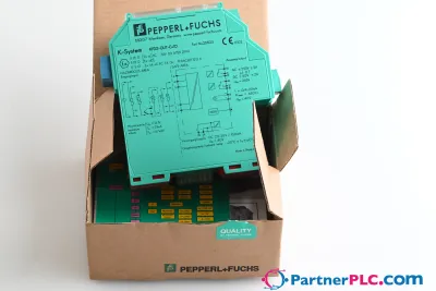 NewPepperl + Fuchs KFD2-GUT-EX1.D New open box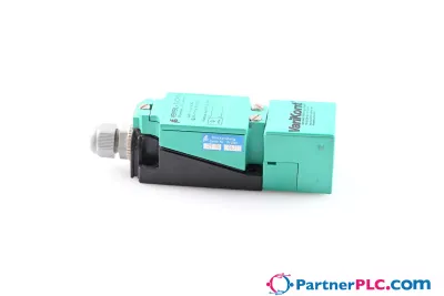
 Available on requestPepperl Fuchs V19-W-BK15M-PUR-U-V19-G
 Available on requestPepperl Fuchs V1SD-G-GN65M-PUR-E1S-V45-G