




.svg&w=240)


















WS0-XTIO84202 Mitsubishi MELSEC-QS/WS Safety Safety I/O
Request a Quote



Quick facts
| Availability | Confirmed on request |
| Category | Mitsubishi MELSEC-QS/WS Safety – Safety controller |
| Lifecycle | Active |
| Warranty | 12-month (new) · 3-month (used/refurbished) |
Shipping & availability
When can WS0-XTIO84202 be shipped?
WS0-XTIO84202 is sourced on request — request a quote and we'll confirm the exact availability and shipping timeline for this specific unit.
Can I pick up WS0-XTIO84202 in person?
Local pickup from our Groningen, Netherlands warehouse may be possible — contact us before ordering to check availability and arrange a collection time.
Is express delivery available?
Yes — mention it when you request a quote for WS0-XTIO84202 and we'll include express shipping options in our reply.
My factory is down and I need this urgently — can you help?
For a critical breakdown, contact us directly at +31 (0)50-7110348 or sales@partnerplc.com — we can look into same-day courier or dedicated taxi/hotshot delivery for WS0-XTIO84202, subject to availability and destination.
The Mitsubishi Electric WS0-XTIO84202 is a safety I/O in the MELSEC-QS/WS Safety. Safety input: 8 points (single-channel)/4 points (dual-channel), safety output: 4 points (single-channel)/2 points (dual-channel), spring-clamp terminal block, fast shut off function Abbreviation: WS0-XTIO Powered by SICK. Specifications and manuals below are Mitsubishi Electric's own data.
Specifications
Product
| Series | MELSEC-QS/WS Safety |
| Category | Safety I/O |
| Type | Safety I/O |
| Outline | Safety input: 8 points (single-channel)/4 points (dual-channel), safety output: 4 points (single-channel)/2 points (dual-channel), spring-clamp terminal block, fast shut off function Abbreviation: WS0-XTIO Powered by SICK |
Specifications
| Safety Integrity Level | SIL3 (IEC 61508, IEC 62061) |
| Category | Category 4 (EN/ISO 13849-1) |
| Performance Level | PLe (EN/ISO 13849-1) |
| PFHd (mean probability of a dangerous failure per hour): Input configuration (I1…I8): Dual channel output | 2.5 × 10 -9 |
| PFHd (mean probability of a dangerous failure per hour): Input configuration (I1…I8): Single channel output with test pulses enabled for all outputs | 6.0 × 10 -9 |
| TM (mission time) | 20 years (EN/ISO 13849-1) |
| Protection degree | Terminals: IP 20 (IEC 60529) Housing: IP 40 (IEC 60529) |
| Electromagnetic compatibility | Class A (EN 61000-6-2, EN 61000-6-4) |
| Power input via FLEXBUS+ without currents to X1, X2 | Maximum 2.8 W |
| Data interface | Backplane bus (FLEXBUS+) |
| External interface | Dual level spring clamp terminals |
| External dimensions: Height | 106.5 mm |
| External dimensions: Width | 22.5 mm |
| External dimensions: Depth | 120.8 mm |
| Weight | 180 g |
| External supply power: Supply voltage | 24 V DC (16.8...30 V DC) |
| External supply power: Type of supply voltage | PELV or SELV The current of the power supply unit for the main module has to be limited to a maximum of 4 A either by the power supply unit itself or by a fuse |
| External supply power: Power consumption | Maximum 96 W, determined by the load at the outputs Q1 to Q4 |
| External supply power: Switch-on time | Maximum 18 s |
| External supply power: Short-circuit protection | 4 A gG (with tripping characteristic B or C) |
| Input circuit (I1...I8): Number of inputs | 8 |
| Input circuit (I1...I8): Input voltage HIGH | 13...30 V DC |
| Input circuit (I1...I8): Input voltage LOW | -5...+5 V DC |
| Input circuit (I1...I8): Input current HIGH | 2.4...3.8 mA |
| Input circuit (I1...I8): Input current LOW | -2.5...2.1 mA |
| Input circuit (I1...I8): Input reverse current in case of ground interruption | Maximum 20 mA 1.5 kΩ effective reverse resistance to power supply |
| Input circuit (I1...I8): Switching current (with mechanical contacts) | 14.4 mA at 5 V 3 mA at 24 V |
| Input circuit (I1...I8): Input capacitance | Maximum 10 nF |
| Input circuit (I1...I8): Discrepancy times | 4 ms...30 s, configurable |
| Test outputs (X1, X2): Number of output points | 2 (with 2 test pulse generators) |
| Test outputs (X1, X2): Output type | PNP semiconductor, short-circuit protected, short-circuit monitoring (selectable) |
| Test outputs (X1, X2): Output voltage High | 16...30 V DC |
| Test outputs (X1, X2): Output resistance Low | 22 Ω +/- 10 %, current limited at approx. 10 mA |
| Test outputs (X1, X2): Output current | Maximum 120 mA at a test output (X1 or X2) This means that a maximum of 8 testable sensor cascades per module with maximum 30 mA each are possible. The total current of the MELSEC-WS safety controller is limited to a maximum of 1.28 A. This corresponds to e.g. a maximum of 32 testable sensor cascades with 30 mA each plus 64 tactile sensors to inputs of safety I/O modules with maximum 5 mA each. |
| Test outputs (X1, X2): Test pulse rate (test period) | 1...25 Hz, configurable |
| Test outputs (X1, X2): Test pulse duration (test gap) | 1...100 ms, configurable |
| Test outputs (X1, X2): Load capacity | 1 µF for test gap ≥ 4 ms 0.5 µF for test gap 1 ms |
| Safety outputs (Q1...Q4): Number of output points | 4 |
| Safety outputs (Q1...Q4): Output type | PNP semiconductor, short-circuit protected, short-circuit monitoring (selectable) |
| Safety outputs (Q1...Q4): Output voltage High | 15.6...30 V DC |
| Safety outputs (Q1...Q4): Leakage current Low: Normal operation | Maximum 0.1 mA |
| Safety outputs (Q1...Q4): Leakage current Low: Fault case | Maximum 1.6 mA |
| Safety outputs (Q1...Q4): Output current | Maximum 2 A |
| Safety outputs (Q1...Q4): Total current Isum: TA ≤ 45 ˚C | Maximum 4.0 A |
| Safety outputs (Q1...Q4): Total current Isum: TA ≤ 55 ˚C | Maximum 3.2 A |
| Safety outputs (Q1...Q4): Total current Isum: For UL/CSA applications | Maximum 3.2 A |
| Safety outputs (Q1...Q4): Test pulse rate | Maximum 5 Hz |
| Safety outputs (Q1...Q4): Load capacity | ≤ 0.5 µF |
| Safety outputs (Q1...Q4): Cable resistance | Maximum 5 Ω |
| Safety outputs (Q1...Q4): Max. permitted coil energy without external protection elements: Hardware version V1.00 | 0.22 J |
| Safety outputs (Q1...Q4): Max. permitted coil energy without external protection elements: Hardware version V1.01 | 0.37 J |
| Safety outputs (Q1...Q4): Response time | Depending on the logic configuration |
| Safety outputs (Q1...Q4): Data interface | Backplane bus(FLEXBUS+) |
Specifications
| General specifications | Refer to the general specifications of the CPU module. |
Downloads & documentation
Official documents from Mitsubishi Electric (Factory Automation), downloaded directly from the manufacturer.
Data sheets & manuals
| Safety Controller User's Manual (SH-080855ENG-P) | PDF · 7.01MB |
| Safety Controller Safety I/O Module User's Manual (Hardware) (IB-0800529ENG-I) | PDF · 0.57MB |
| WARRANTY (BCN-P5736) | PDF · 0.08MB |
More Mitsubishi Electric (Factory Automation) parts
 Available on requestWS0-TBC4 Mitsubishi MELSEC-QS/WS Safety Option
 Available on requestWS0-TBS4 Mitsubishi MELSEC-QS/WS Safety Option
 Available on requestWS0-UC-232A Mitsubishi MELSEC-QS/WS Safety CPU
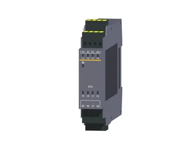 Available on requestWS0-XTDI80202 Mitsubishi MELSEC-QS/WS Safety Safety I/O