




.svg&w=240)


















Q170MSCPU-S1 Mitsubishi Motion controller
Request a Quote



Quick facts
| Availability | Confirmed on request |
| Category | Mitsubishi Motion controller – Motion Controller |
| Lifecycle | Active mature |
| Warranty | 12-month (new) · 3-month (used/refurbished) |
Shipping & availability
When can Q170MSCPU-S1 be shipped?
Q170MSCPU-S1 is sourced on request — request a quote and we'll confirm the exact availability and shipping timeline for this specific unit.
Can I pick up Q170MSCPU-S1 in person?
Local pickup from our Groningen, Netherlands warehouse may be possible — contact us before ordering to check availability and arrange a collection time.
Is express delivery available?
Yes — mention it when you request a quote for Q170MSCPU-S1 and we'll include express shipping options in our reply.
My factory is down and I need this urgently — can you help?
For a critical breakdown, contact us directly at +31 (0)50-7110348 or sales@partnerplc.com — we can look into same-day courier or dedicated taxi/hotshot delivery for Q170MSCPU-S1, subject to availability and destination.
The Mitsubishi Electric Q170MSCPU-S1 is a motion controller in the Motion controller. Stand-alone type (a power supply, PLC CPU, and Motion CPU are integrated), Maximum number of control axes: 16 axes, SSCNET III/H connection. Mitsubishi Electric has announced its discontinuation (2029/09 To be end of order) — plan spares now; PartnerPLC also sources it on the surplus market after the end of order. Specifications and manuals below are Mitsubishi Electric's own data.
Specifications
Product
| Series | Motion controller |
| Category | Motion controller |
| Type | MELSEC Q series |
| Subtype | CPU module |
| Sales status | 2029/09 To be end of order (Mitsubishi Electric) |
| Outline | Stand-alone type (a power supply, PLC CPU, and Motion CPU are integrated), Maximum number of control axes: 16 axes, SSCNET III/H connection |
Control specifications
| Number of control axes | Up to 16 axes |
| Operation cycle (operation cycle settings) | 0.22 ms, 0.44 ms, 0.88 ms, 1.77 ms, 3.55 ms, 7.11 ms |
| Interpolation function | Linear interpolation (up to 4 axes), 2-axis circular interpolation, helical interpolation (3 axes) |
| Control method | Positioning control, speed control, speed-position switching control, fixed-pitch feed, constant speed control, position follow-up control, speed control with fixed position stop, speed switching control, high-speed oscillation control, synchronous control (SV22 (advanced synchronous control method/virtual mode switching method)), cam control (SV22), speed-torque control |
| Acceleration/deceleration processing | Trapezoidal acceleration/deceleration, S-curve acceleration/deceleration, advanced S-curve acceleration/deceleration |
| Compensation function | Backlash compensation, electronic gear, phase compensation (SV22) |
| Programming language | Motion SFC, dedicated instruction, mechanical support language (SV22) |
| Servo program capacity | 16k steps |
| Number of positioning points | 3200 points (positioning data can be set indirectly) |
| PERIPHERAL I/F: Motion CPU area | PERIPHERAL I/F |
| PERIPHERAL I/F: PLC CPU area | USB, RS-232 |
| Home position return function | Proximity dog method (2 types), count method (3 types), data set method (2 types), dog cradle method, stopper method (2 types), limit switch combined method, scale home position signal detection method, dogless home position signal reference method (home position return re-try function provided, home position shift function provided) |
| JOG operation function | Provided |
| Manual pulse generator operation function | Possible to connect 3 modules (Q173DPX use), Possible to connect 1 module (internal I/F use) *4 |
| Speed-torque control | Speed control not including position loop, torque control, continuous operation to torque control |
| Synchronous encoder operation function | 12 modules connectable (SV22) (via Q173DPX + internal I/F + device *5 + servo amplifier *5 ) |
| M-code function | M-code output function provided, M-code completion wait function provided |
| Limit switch output function | Number of output points: 64 points (Advanced synchronous control method), 32 points (virtual mode switching method (SV13)) Watch data: Motion control data, word device |
| ROM operation function | Provided |
| External input signal | Q172DLX (FLS, RLS, STOP, DOG), external input signals (FLS, RLS, DOG) of servo amplifier, internal I/F (DI), bit device |
| High-speed reading function *5 | Available (via input module, built-in interface in Motion CPU, tracking of Q173DPX) |
| Mark detection function | Continuous detection mode, specified number of detections mode, ring buffer mode |
| Mark detection function: Mark detection signal | 4 points (via Internal I/F), bit device, Q172DLX (DOG) |
| Mark detection function: Mark detection setting | 32 settings |
| Torque limit value change function | Torque limit value (positive/negative direction) |
| Target position change function | Provided |
| Servo parameter change function | Provided |
| Servo amplifier control mode switching function | Gain switching function, PI-PID control, control loop changing (fully closed loop control, semi closed loop control) |
| Optional data monitor function | Up to 6 data/axis (MR-J4-B with SSCNET III/H use) |
| Forced stop | Motion controller forced stop (EMI connector, system setting), forced stop terminal of servo amplifier |
| Number of I/O points | Total of 256 points (internal I/F (4 input points) + I/O module + intelligent function module) |
| Clock function | Provided |
| Security function | Password registration, password for every Motion SFC program, software security key function |
| All clear function | Delete all user data in Motion CPU |
| Remote operation | Remote RUN/STOP, remote latch clear |
| Digital oscilloscope function | Bit data: 16 channels, word data: 16 channels *3 |
| Driver communication function | Provided |
| Amplifier-less operation function | Provided |
| Absolute position system | Made compatible by setting battery to servo amplifier. (Possible to select the absolute data method or incremental method for each axis) |
| Number of SSCNET III/H lines *1 | 1 line |
| Number of Motion modules | Q172DLX: 2 modules usable Q173DPX: 4 modules usable *2 |
Module specifications
| Number of control axes | Up to 16 axes |
| PLC CPU area | Q06UDHCPU or equivalent |
| Program capacity | 60k steps (240 k bytes) |
| Servo amplifier connection method | SSCNET III/H (1 line) |
| Maximum overall cable distance [m] | SSCNET III/H: 1600, SSCNET III: 800 |
| Maximum distance between stations [m] | SSCNET III/H: 100, SSCNET III: 50 |
| PERIPHERAL I/F | PERIPHERAL I/F (Motion CPU area control), USB/RS-232/Ethernet (PLC CPU area control) |
| Manual pulse generator operation function | Possible to connect 3 modules of manual pulse generator |
| Synchronous encoder operation function | Possible to connect 12 modules *6 (SV22 use) |
| Controllable modules: Q172DLX | Up to 2 modules |
| Controllable modules: Q173DPX | Up to 4 modules per CPU (incremental synchronous encoder use in SV22) Up to 1 module per CPU (only manual pulse generator use) |
| Controllable modules: Input/output module Analog module | Total: up to 256 points per CPU |
| Controllable modules: QI60 | Up to 1 module |
| Input signal: Number of input points | 4 points |
| Input signal: Input method | Positive common/negative common shared type (photocoupler isolation) |
| Input signal: Rated input voltage/current | 24 V DC/Approx. 5 mA |
| Input signal: Operating voltage range | 20.4 V DC to 26.4 V DC (+10 %/-15 %, ripple ratio 5 % or less) |
| Input signal: ON voltage/current | 17.5 V DC or more/3.5 mA or more |
| Input signal: OFF voltage/current | 5 V DC or less/0.9 mA or less |
| Input signal: Input resistance | Approx. 5.6 kΩ |
| Input signal: Response time | 1 ms or less (OFF to ON, ON to OFF) |
| Input signal: Recommended wire size | AWG 18 to AWG 22 |
| Forced stop input signal: Number of input points | 1 point |
| Forced stop input signal: Input method | Sink/source (photocoupler isolation) |
| Forced stop input signal: Rated input voltage/current | 24 V DC/Approx. 2.4 mA |
| Forced stop input signal: Operating voltage range | 20.4 V DC to 26.4 V DC (+10 %/-15 %, ripple ratio 5 % or less) |
| Forced stop input signal: ON voltage/current | 17.5 V DC or more/2.0 mA or more |
| Forced stop input signal: OFF voltage/current | 1.8 V DC or less/0.18 mA or less |
| Forced stop input signal: Input resistance | Approx. 10 kΩ |
| Forced stop input signal: Response time | 1 ms or less (OFF to ON, ON to OFF) |
| Forced stop input signal: Recommended wire size | AWG 16 to AWG 22 |
| Manual pulse generator/incremental synchronous encoder signal: Signal input form | Phase A/phase B (magnification by 4) |
| Manual pulse generator/incremental synchronous encoder signal: Maximum input pulse frequency | Up to 1 Mpps (after magnification by 4, up to 4 Mpps) (differential-output type) Up to 200 kpps (after magnification by 4, up to 800 kpps) (voltage-output/open-collector type) |
| Memory card interface | Internal interface |
| Number of stages of extension base | Up to 7 stages |
| 24 V DC internal current consumption [A] | 1.4 |
| Mass [kg] | 0.8 |
| Exterior dimensions [mm] | 186.0 (H) × 52.0 (W) × 135.0 (D) |
Downloads & documentation
Official documents from Mitsubishi Electric (Factory Automation), downloaded directly from the manufacturer.
Data sheets & manuals
More Mitsubishi Electric (Factory Automation) parts
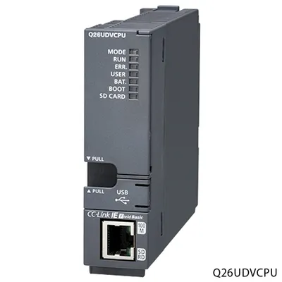 Available on requestQ13UDVCPU Mitsubishi MELSEC-Q Series Programmable controller CPU
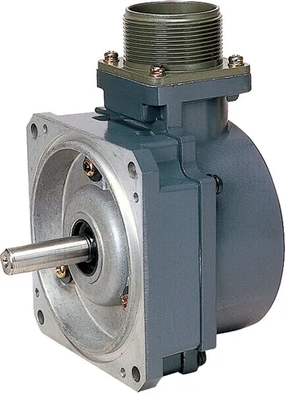 Available on requestQ170ENC Mitsubishi Motion controller
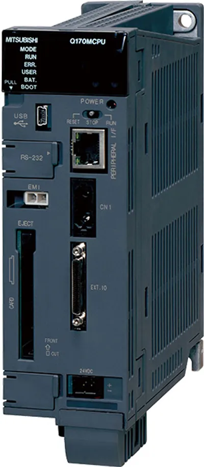 Available on requestQ170MCPU Mitsubishi Motion controller
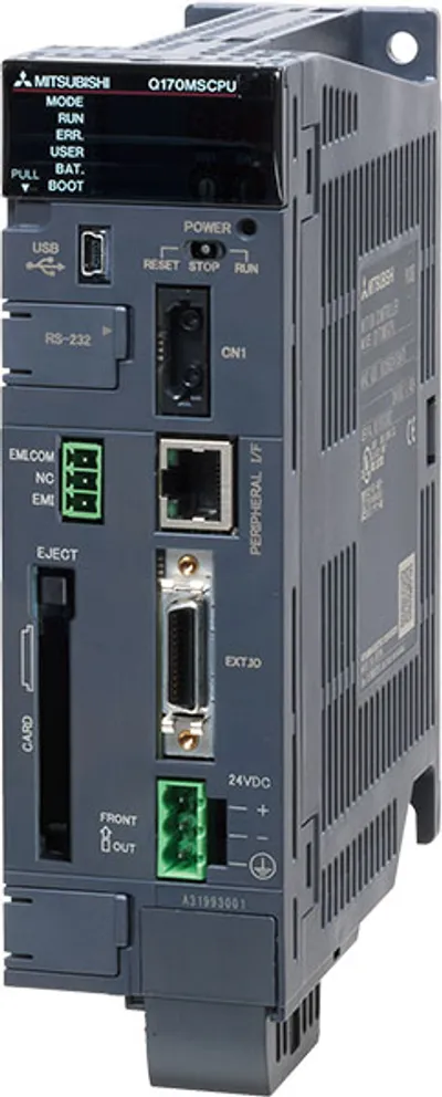 Available on requestQ170MSCPU Mitsubishi Motion controller
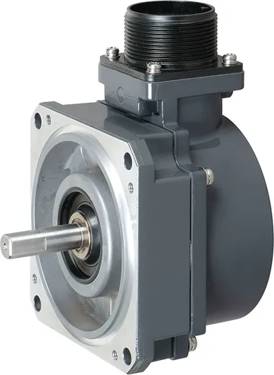 Available on requestQ171ENC-W8 Mitsubishi Motion controller
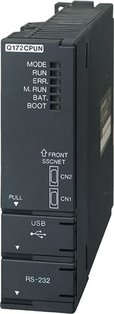 Available on requestQ172CPUN Mitsubishi MELSEC-Q Series Motion CPU
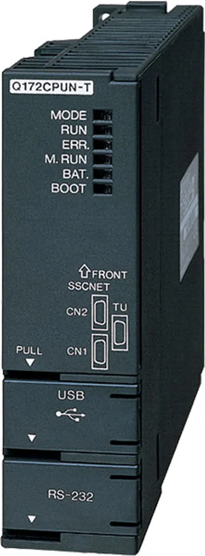 Available on requestQ172CPUN-T Mitsubishi MELSEC-Q Series Motion CPU
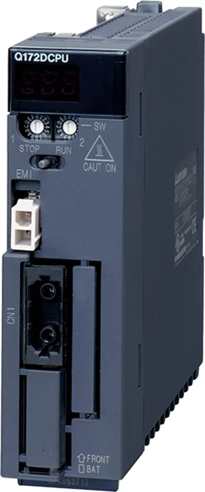 Available on requestQ172DCPU Mitsubishi MELSEC-Q Series Motion CPU