




.svg&w=240)


















FX3G-40MR/DS Mitsubishi MELSEC-F (FX) Series Main unit
Request a Quote



Quick facts
| Availability | Confirmed on request |
| Category | Mitsubishi MELSEC-F (FX) Series – Main Unit |
| Lifecycle | Active mature |
| Warranty | 12-month (new) · 3-month (used/refurbished) |
Shipping & availability
When can FX3G-40MR/DS be shipped?
FX3G-40MR/DS is sourced on request — request a quote and we'll confirm the exact availability and shipping timeline for this specific unit.
Can I pick up FX3G-40MR/DS in person?
Local pickup from our Groningen, Netherlands warehouse may be possible — contact us before ordering to check availability and arrange a collection time.
Is express delivery available?
Yes — mention it when you request a quote for FX3G-40MR/DS and we'll include express shipping options in our reply.
My factory is down and I need this urgently — can you help?
For a critical breakdown, contact us directly at +31 (0)50-7110348 or sales@partnerplc.com — we can look into same-day courier or dedicated taxi/hotshot delivery for FX3G-40MR/DS, subject to availability and destination.
The Mitsubishi Electric FX3G-40MR/DS is a main unit in the MELSEC-F (FX) Series. DC Power Supply/DC Input Type Input: 24 points 24 V DC sink/source Output: 16 points Relay. Mitsubishi Electric has announced its discontinuation (2026/12 To be discontinued) — plan spares now; PartnerPLC also sources it on the surplus market after the end of order. Specifications and manuals below are Mitsubishi Electric's own data.
Specifications
Product
| Series | MELSEC-F (FX) Series |
| Category | Main unit |
| Sales status | 2026/12 To be discontinued (Mitsubishi Electric) |
| Outline | DC Power Supply/DC Input Type Input: 24 points 24 V DC sink/source Output: 16 points Relay |
Specifications
| Operation control system | Stored program repetitive operation system with interruption function |
| Input/output control system | Batch processing system (when END instruction is executed), Input/output refresh instruction and pulse catch function are provided. |
| Programming language | Relay symbol system + step-ladder system (SFC notation possible) |
| Program memory: Max. memory capacity | 32000 steps 32000 steps including comments and file registers |
| Program memory: Built-in memory capacity/type | 32000 steps EEPROM (memory backup not required) |
| Program memory: Memory cassette (Option) | FX3G-EEPROM-32L (32000 steps EEPROM) |
| Program memory: Writing function during running | Provided (Program can be modified while the PLC is running.) |
| Program memory: Protection | With keyword/Customer keyword function |
| Real-time clock: Clock function | Built-in 1980 to 2079 (with correction for leap year), 2- or 4-digit year, accuracy within ±45 seconds/month at 25°C *Precaution for clock function The current time of the built-in clock is backed up by a high-capacity capacitor (built-in). The large-capacity capacitor (built-in) fully charges in 30 minutes and retains the current value for ten days. The optional battery can also be used to hold t |
| Kinds of instructions: Basic instructions | ・Sequence instructions: 29 ・Step-ladder instructions: 2 |
| Kinds of instructions: Applied instructions | Applied instructions: 121 kinds |
| Processing speed: Basic instructions | Standard mode: 0.21 μs/instruction (if the capacity for programming is set to less than 16000 steps) Extension mode: 0.42 μs/instruction (if the capacity for programming is set to more than 16001 steps) |
| Processing speed: Applied instructions | Standard mode: 0.5 μs to several hundred μs/instruction (if the capacity for programming is set to less than 16000 steps) Extension mode: 1.2 μs to several hundred μs/instruction (if the capacity for programming is set to more than 16001 steps) |
| No. of input/output points: No. of input points | (1) 128 points or less (Extension-combined) Total of (1)+(2): 128 points or less |
| No. of input/output points: No. of output points | (2) 128 points or less (Extension-combined) Total of (1)+(2): 128 points or less |
| No. of input/output points: Remote I/O number of points: CC-Link | (3) 128 points or less *The total number of remote I/O points in CC-Link and AnyWireASLINK must be 128 points or less. |
| No. of input/output points: Remote I/O number of points: AnyWireASLINK | (3) 128 points or less *The total number of remote I/O points in CC-Link and AnyWireASLINK must be 128 points or less. |
| No. of input/output points: Total number of points | Total of (1)+(2)+(3): 256 points or less (Extension-combined) |
| Device: Input/output relay: Input relay | X000 to X177 128 points (octal) Extension-combined |
| Device: Input/output relay: Output relay | Y000 to Y177 128 points (octal) Extension-combined |
| Device: Auxiliary relay: For general | M0 to M383 384 points |
| Device: Auxiliary relay: For keeping (EEPROM keep) | M384 to M1535 1152 points |
| Device: Auxiliary relay: For general-purpose (can be changed to keeping) | M1536 to M7679 6144 points These devices can be changed to the keep (battery backup) type using a parameter when the optional battery is used. *Precaution for the retentive status The retentive status other than M1536 to M7679 is fixed. (Cannot be changed with parameter) |
| Device: Auxiliary relay: For special | M8000 to M8511: 512 points |
| Device: State: Initial state (EEPROM keep) | S0 to S9 10 points |
| Device: State: For keeping (EEPROM keep) | S10 to S999 990 points |
| Device: State: For general | S1000 to S4095 3096 points These devices can be changed to the keep (battery backup) type using a parameter when the optional battery is used. |
| Device: Timer (on delay): 100 ms | T0 to T191: 192 points (0.1 to 3,276.7 sec) |
| Device: Timer (on delay): 100 ms (for subroutine/interruption subroutine) | T192 to T199: 8 points (0.1 to 3,276.7 sec) |
| Device: Timer (on delay): 10 ms | T200 to T245: 46 points (0.01 to 327.67 sec) |
| Device: Timer (on delay): 1 ms accumulating type (EEPROM keep) | T246 to T249 4 points (0.001 to 32.767 sec) *Precaution for the retentive status The retentive status is fixed. (Cannot be changed with parameter) |
| Device: Timer (on delay): 100 ms accumulating type (EEPROM keep) | T250 to T255 6 points (0.1 to 3,276.7 sec) *Precaution for the retentive status The retentive status is fixed. (Cannot be changed with parameter) |
| Device: Timer (on delay): 1 ms | T256 to T319 64 points (0.001 to 32.767 sec) |
| Device: Timer (on delay): Others | Available as analog timers VR1: D8030, VR2: D8031 2 points (0 to 255) |
| Device: Counter: 16 bits up | C0 to C15 16 points (Counting from 0 to 32,767) |
| Device: Counter: 16 bits up (EEPROM keep) | C16 to C199 184 points (Counting from 0 to 32,767) *Precaution for the retentive status The retentive status is fixed. (Cannot be changed with parameter) |
| Device: Counter: 32 bits up or down | C200 to C219 20 points (Counting from -2,147,483,648 to +2,147,483,647) |
| Device: Counter: 32 bits up/down (EEPROM keep) | C220 to C234 15 points (Counting from -2,147,483,648 to +2,147,483,647) *Precaution for the retentive status The retentive status is fixed. (Cannot be changed with parameter) |
| Device: High-speed counter | [32 bits high-speed up/down (EEPROM keep)] Up to 6 points can be used between C235 and C255. 1-phase: 60 kHz, 10 kHz 2-phase: 30 kHz, 5 kHz The number of points that can be used and the input frequency are limited depending on the conditions of use. |
| Device: Data register (32 bits when paired): 16 bits for general | D0 to D127 128 points |
| Device: Data register (32 bits when paired): For 16 bits keep (EEPROM keep) | D128 to D1099 972 points |
| Device: Data register (32 bits when paired): For 16 bits general (can be changed to keeping) | D1100 to D7999 6900 points These devices can be changed to the keep (battery backup) type using a parameter when the optional battery is used. |
| Device: Data register (32 bits when paired): File register (EEPROM keep) | D1000 to D7999 Maximum 7000 points (Can be set as file registers in units of 500 points from D1000 in the program area (EEPROM) using parameters.) |
| Device: Data register (32 bits when paired): 16 bits for special | D8000 to D8511: 512 points |
| Device: Data register (32 bits when paired): 16 bits for index | V0 to V7, Z0 to Z7: 16 points |
| Device: Extension register: For 16 bits general (can be changed to keeping) | R0 to R23999 24000 points These devices can be changed to the keep (battery backup) type using a parameter when the optional battery is used. |
| Device: Extension file register: 16 bits (EEPROM keep) | ER0 to ER23999 24000 points Stored in the EEPROM built-in the main unit, or stored in the EEPROM in the memory cassette when the memory cassette is used. |
| Device: Pointer: For branching of JUMP and CALL | P0 to P2047 2048 points (For CJ instructions and CALL instructions, P63 jumps to END instruction) |
| Device: Pointer: Input interruption | I00□ to I50□: 6 points |
| Device: Pointer: Timer interruption | I6□□ to I8□□: 3 points |
| Device: Nesting | [For master control] N0 to N7: 8 points (For MC instructions) |
| Constant: Decimal number (K) | 16 bits: -32,768 to +32,767 32 bits: -2,147,483,648 to +2,147,483,647 |
| Constant: Hexadecimal number (H) | 16 bits: 0 to FFFF 32 bits: 0 to FFFFFFFF |
| Constant: Real number (E) | 32 bits: -1.0 × 2 128 to -1.0 × 2 -126 , 0, 1.0 × 2 -126 to 1.0 × 2 128 Decimal-point and exponential notations are possible. |
Power supply specifications
| Rated voltage | 24 V DC |
| Allowable supply voltage range | 20.4 V to 28.8 V DC |
| Frequency rating | - |
| Allowable instantaneous power failure time | Operation can be continued upon occurrence of instantaneous power failure for 5 ms or less. |
| Power fuse | 125V 3.15 A |
| Rush current | 30 A max. 1ms or less/24 V DC |
| Power consumption | 25 W |
| 24 V DC service power supply | - |
Input specifications
| No. of input points | 24 points |
| Input connection type | Removable terminal block (M3 screw) |
| Input type | Sink/source |
| Input signal voltage | 20.4 to 28.8 V DC |
| Input impedance: X000 to X007 | 3.3 kΩ |
| Input impedance: X010 or more | 4.3 kΩ |
| Input signal current: X000 to X007 | 7 mA/24 V DC |
| Input signal current: X010 or more | 5 mA/24 V DC |
| ON input sensitivity current: X000 to X007 | 4.5 mA or more |
| ON input sensitivity current: X010 or more | 3.5 mA or more |
| OFF input sensitivity current | 1.5 mA or less |
| Input response time | Approx. 10 ms X000 to X007 have built-in digital filters, which can be changed to 0 to 15 ms in 1 ms increments using the application instructions or D8020. The following is applied when 0 is set. X000, X001, X003, X004: 10 μs X002, X005, X006, X007: 50 μs |
| Input signal form | No-voltage contact input Sink: NPN open collector transistor Source: PNP open collector transistor |
| Input circuit insulation | Photocoupler insulation |
| Indication of input operation | When photocoupler is driven, LED on panel is lit. |
Output specifications
| No. of output points | 16 points |
| Output connection type | Removable terminal block (M3 screw) |
| Output type | Relay output |
| External power supply | 30 V DC or less, 240 V AC or less (250 V AC or less when the unit does not comply with CE, UL or cUL standards) |
| Max. load: Resistance load | 2 A/1 point The total load current per common terminal should be the following value. 1 output point/common terminal: 2 A or less 4 output points/common terminal: 8 A or less |
| Max. load: Inductive load | 80 VA |
| Min. load | 5 V DC, 2 mA (reference value) |
| Open circuit leakage current | - |
| ON voltage | - |
| Response time: OFF→ON | Approx. 10 ms |
| Response time: ON→OFF | Approx. 10 ms |
| Insulation of circuit | Mechanical insulation |
| Indication of output operation | When power is applied to relay coil, LED on panel is lit. |
Built-in high-speed counter function
| 1-phase 1-count input | [C235, C236] 60 kHz [C237] 10 kHz [C238, C239] 60 kHz [C240] 10 kHz [C241] 60 kHz [C242 to C245] 10 kHz When using multiple high-speed counters, make sure that the sum of used frequency does not exceed the overall frequency. |
| 1-phase 2-count input | [C246, C248(OP)] 60 kHz [C247, C248] 10 kHz [C249, C250] 10 kHz When using multiple high-speed counters, make sure that the sum of used frequency does not exceed the overall frequency. |
| 2-phase 2-count input | [C251, C253(OP)] 30 kHz [C254(OP)] 5 kHz [C252, C253] 5 kHz [C254, C255] 5 kHz When using multiple high-speed counters, make sure that the sum of used frequency does not exceed the overall frequency. |
Specifications
| Ambient temperature | 0 to 55°C (32 to 131°F) when operating and -25 to 75°C (-13 to 167°F) when stored |
| Ambient humidity | 5 to 95%RH (no condensation) when operating |
| Vibration resistance: Installed on DIN rail: Frequency: 10 to 57 Hz | Half amplitude: 0.035mm Sweep Count for X, Y, Z: 10 times (80 min in each direction) The criterion is shown in IEC61131-2. |
| Vibration resistance: Installed on DIN rail: Frequency: 57 to 150 Hz | Acceleration: 4.9 m/s 2 Sweep Count for X, Y, Z: 10 times (80 min in each direction) The criterion is shown in IEC61131-2. |
| Vibration resistance: Direct installing: Frequency: 10 to 57 Hz | Half amplitude: 0.075 mm Sweep Count for X, Y, Z: 10 times (80 min in each direction) The criterion is shown in IEC61131-2. |
| Vibration resistance: Direct installing: Frequency: 57 to 150 Hz | Acceleration: 9.8 m/s 2 Sweep Count for X, Y, Z: 10 times (80 min in each direction) The criterion is shown in IEC61131-2. |
| Shock resistance | 147 m/s 2 Acceleration, Action time: 11 ms, 3 times by half-sine pulse in each direction X, Y, and Z The criterion is shown in IEC61131-2. |
| Noise resistance | By noise simulator at noise voltage of 1,000 Vp-p, noise width of 1 μs, rise time of 1 ns and period of 30 to 100 Hz |
| Dielectric withstand voltage | Perform dielectric withstand voltage test at the following voltage between each terminals and the main unit ground terminal. Between power supply terminal (DC power supply) and ground terminal: 500 V AC for 1 min Between output terminal (relay) and ground terminal: 1.5 kV AC for 1 min |
| Insulation resistance | Perform insulation resistance test at the following voltage between each terminals and the main unit ground terminal. Between power supply terminal (DC power supply) and ground terminal: 5 MΩ or higher by 500 V DC insulation resistance tester Between output terminal (relay) and ground terminal: 5 MΩ or higher by 500 V DC insulation resistance tester |
| Grounding | Class D grounding (grounding resistance: 100 Ω or less) (Common grounding with a heavy electrical system is not allowed) Ground the PLC independently or jointly. |
| Working atmosphere | Free from corrosive or flammable gas and excessive conductive dusts |
| Working altitude | 2000 m or less Do not use the PLC under pressure higher than the atmospheric pressure. Doing so may damage the PLC. |
Downloads & documentation
Official documents from Mitsubishi Electric (Factory Automation), downloaded directly from the manufacturer.
Data sheets & manuals
| FX3G SERIES HARDWARE MANUAL (JY997D46001) | PDF · 0.75MB |
| FX3G SERIES USER'S MANUAL - Hardware Edition (JY997D31301-U) | PDF · 12.18MB |
More Mitsubishi Electric (Factory Automation) parts
 Available on requestFX3G-24MT/ES Mitsubishi MELSEC-F (FX) Series Main unit
 Available on requestFX3G-24MT/ESS Mitsubishi MELSEC-F (FX) Series Main unit
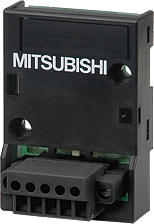 Available on requestFX3G-2AD-BD Mitsubishi MELSEC-F (FX) Series Analog
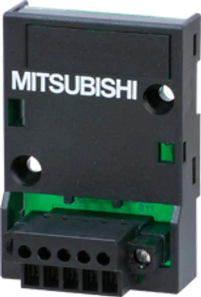 Available on requestFX3G-2EYT-BD Mitsubishi MELSEC-F (FX) Series Input/output extension
 Available on requestFX3G-40MR/ES Mitsubishi MELSEC-F (FX) Series Main unit
 Available on requestFX3G-40MT/DS Mitsubishi MELSEC-F (FX) Series Main unit
 Available on requestFX3G-40MT/DSS Mitsubishi MELSEC-F (FX) Series Main unit
 Available on requestFX3G-40MT/ES Mitsubishi MELSEC-F (FX) Series Main unit