




.svg&w=240)


















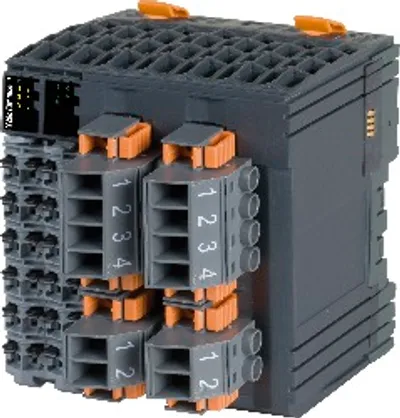
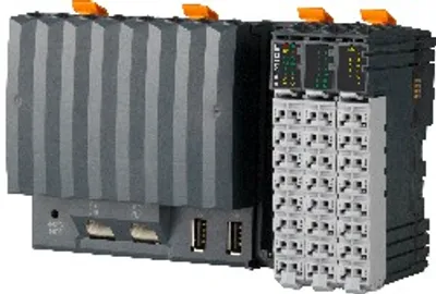
B&R X20cCP1301
Interfaces, 1x RS232, 1x Ethernet, 1x USB, 1x X2X Link
- MPN
- X20cCP1301
- Category
- Compact PLC
Price and lead time confirmed within 1 business day
Request a Quote
- 12-month warranty (new) · 3-month (used/refurbished)
- 30-day returns, no restocking fee on unused parts
- Ships via



What is the B&R X20cCP1301?
Intel x86 200 MHz compatible with integrated I/O processor
Onboard Ethernet and USB
1 slot for modular interface expansion
30 digital inputs/outputs and 2 analog inputs integrated in the device
1 GB onboard flash drive
128 MB DDR3 SDRAM
Fanless
No battery
Backed-up real-time clock
The X20 Compact controller series is characterized by 3 integrated I/O modules. The device is equipped with 30 different digital inputs/outputs and 2 analog inputs . 1 analog input can be used for Pt1000 resistance temperature measurement.
The X20CP1301 is equipped with an Intel x86 200 MHz compatible processor, 128 MB RAM and 1 GB built-in flash drive. The FRAM for storing remanent variables has 16 kB available. A fanless and battery-free design ensures maintenance-free operation.
The controller is equipped with one Ethernet, one USB and one RS232 interface. Various bus and network systems can be flexibly integrated into the X20 system via a freely usable slot for X20 communication modules.
Specifications
Short description
| Interfaces | 1x RS232, 1x Ethernet, 1x USB, 1x X2X Link |
| System module | Controller |
General information
| Diagnostics – Outputs | Digital outputs: Yes, using LED status indicator and software (output error status) |
| Diagnostics – CPU function | Yes, using LED status indicator |
| Diagnostics – RS232 data transfer | Yes, using LED status indicator |
| Diagnostics – Inputs | Analog inputs: Yes, using LED status indicator and software |
| Diagnostics – Ethernet | Yes, using LED status indicator |
| Diagnostics – I/O power supply | Yes, using LED status indicator |
| Diagnostics – Supply voltage monitoring | Yes, using LED status indicator |
| Diagnostics – Temperature | Yes, using software register |
| Support – Controller redundancy | No |
| Support – ACOPOS support | Yes |
| Support – reACTION-capable I/O channels | No |
| Support – Visual Components support | Yes |
| Power consumptionMechanical and electrical configuration" in the X20 system user's manual."> – Internal I/O | 2.3 W (note: The specified values are maximum values. For examples of the exact calculation, see section) |
| Certifications – CE | Yes |
| Certifications – UKCA | Yes |
| Certifications – CRA (Cyber Resilience Act) | Non-compliant |
| Certifications – ATEX | Zone 2, II 3G Ex nA nC IIA T5 Gc; IP20, Ta (see X20 user's manual); FTZÚ 09 ATEX 0083X |
| Certifications – UL | cULus E115267; Industrial control equipment |
| Certifications – HazLoc | cCSAus 244665; Process control equipment; for hazardous locations; Class I, Division 2, Groups ABCD, T5 |
| Certifications – DNV | Temperature: B (0 to 55°C); Humidity: B (up to 100%); Vibration: B (4 g); EMC: B (bridge and open deck) |
| Certifications – LR | ENV1 |
| Certifications – KR | Yes |
| Certifications – ABS | Yes |
| Certifications – BV | EC33B ; Temperature: 5 - 55°C; Vibration: 4 g; EMC: Bridge and open deck |
| B&R ID code | 0xEB58 |
| Cooling | Fanless |
| Status indicators | CPU function, Ethernet, RS232, PLC power supply, I/O power supply, I/O function per channel |
| Power consumption without interface module and USB | 4.3 W |
| Power consumption for X2X Link power supplyMechanical and electrical configuration" in the X20 system user's manual."> | 0.8 W (note: The specified values are maximum values. For examples of the exact calculation, see section) |
| Additional power dissipation caused by actuators (resistive) [W] | - |
| Type of signal lines | Shielded lines must be used for all high-speed digital inputs/outputs, line length: Max. 20 m |
CPU and X2X Link power supply
| Input voltage | 24 VDC -15% / +20% |
| Input current | Max. 1 A |
| Fuse | Integrated, cannot be replaced |
| Reverse polarity protection | Yes |
X2X Link power supply output
| Nominal output power | 2 W |
| Parallel connection | Yes (note: When operated in parallel, the nominal power of 2 W is not permitted to be added to the total power.) |
| Redundant operation | Yes (note: Up to 2 W bus load.) |
Input I/O power supply
| Input voltage | 24 VDC -15% / +20% |
| Fuse | Required line fuse: Max. 10 A, slow-blow |
Output I/O power supply
| Nominal output voltage | 24 VDC |
| Permissible contact load | 10 A |
Controller
| Processor – Data code | 16 kB |
| Processor – Program code | 16 kB |
| Processor – Type | Vx86EX |
| Processor – Clock frequency | 200 MHz |
| Processor – L2 cache | 128 kB |
| Standard memory – RAM | 128 MB DDR3 SDRAM |
| Application memory – Guaranteed | 40 TB |
| Application memory – Results for 5 years | 21.9 GB/day |
| Application memory – Type | 1 GB eMMC flash memory |
| Application memory – Data retention | 10 years |
| Application memory – Guaranteed erase/write cycles | 20,000 |
| Application memory – Error-correcting code (ECC) | Yes |
| Real-time clock | Retention for at least 300 hours, typ. 1000 hours at 25°C, 1 s resolution, -18 to 28 ppm accuracy at 25°C |
| Floating point unit (FPU) | Yes |
| Integrated I/O processor | Processes I/O data points in the background |
| Modular interface slots | 1 |
| Remanent variables | 16 kB FRAM, retention >10 years (note: The memory size for remanent variables is configurable in Automation Studio.) |
| Shortest task class cycle time | 2 ms |
| Typical instruction cycle time | 0.0419 µs |
Interfaces
| Interface IF1 – Signal | RS232 |
| Interface IF1 – Variant | Connection via 16-pin terminal block X20TB1F |
| Interface IF1 – Max. distance | 900 m |
| Interface IF1 – Transfer rate | Max. 115.2 kbit/s |
| Interface IF2 – Physical layer | 10BASE-T/100BASE-TX |
| Interface IF2 – Half-duplex | Yes |
| Interface IF2 – Full-duplex | Yes |
| Interface IF2 – Autonegotiation | Yes |
| Interface IF2 – Auto-MDI/MDIX | Yes |
| Interface IF2 – Signal | Ethernet |
| Interface IF2 – Variant | 1x RJ45 shielded |
| Interface IF2 – Line length | Max. 100 m between 2 stations (segment length) |
| Interface IF2 – Transfer rate | 10/100 Mbit/s |
| Interface IF4 – Type | USB 1.1/2.0 |
| Interface IF4 – Variant | Type A |
| Interface IF4 – Max. output current | 0.5 A |
| Interface IF6 – Fieldbus | X2X Link master |
Digital inputs
| Input filter – Hardware | Standard inputs and mixed channels: ≤200 μs; High-speed inputs: ≤2 μs, when used as standard inputs: ≤200 μs |
| Input filter – Software | Default 1 ms, configurable between 0 and 25 ms in 0.1 ms increments |
| Switching threshold – Low | <5 VDC |
| Switching threshold – High | >15 VDC |
| Quantity | 14 standard inputs, 4 high-speed inputs and 4 mixed channels, configuration as input or output using software |
| Nominal voltage | 24 VDC |
| Input voltage | 24 VDC -15% / +20% |
| Input current at 24 VDC | X1 - Standard inputs: Typ. 3.5 mA; X2 - Standard inputs: Typ. 2.68 mA; X2 - High-speed inputs: Typ. 3.5 mA; X3 - Mixed channels: Typ. 2.68 mA |
| Input circuit | Sink |
| Connection type | 1-wire connections |
| Input resistance | X1 - Standard inputs: 6.8 kΩ; X2 - Standard inputs: 8.9 kΩ; X2 - High-speed inputs: 6.8 kΩ; X3 - Mixed channels: 8.9 kΩ |
| Additional functions | X2 - High-speed digital inputs:; 2x 250 kHz event counting, 2x AB counter, ABR incremental encoder, direction/frequency, period measurement, gate measurement, differential time measurement, edge counters, edge times |
AB incremental encoder
| Quantity | 2 |
| Encoder inputs | 24 V, asymmetrical |
| Counter size | 32-bit |
| Input frequency | Max. 100 kHz |
| Evaluation | 4x |
| Encoder power supply | Module-internal, max. 300 mA |
| Overload characteristics of encoder power supply | Short-circuit proof, overload-proof |
ABR incremental encoder
| Quantity | 1 |
| Encoder inputs | 24 V, asymmetrical |
| Counter size | 32-bit |
| Input frequency | Max. 100 kHz |
| Evaluation | 4x |
| Encoder power supply | Module-internal, max. 300 mA |
| Overload characteristics of encoder power supply | Short-circuit proof, overload-proof |
Event counters
| Quantity | 2 |
| Signal form | Square wave pulse |
| Evaluation | 1x |
| Input frequency | Max. 250 kHz |
| Counter frequency | 250 kHz |
| Counter size | 32-bit |
Edge detection / Time measurement
| Possible measurements | Period measurement, gate measurement, differential time measurement, edge counter, edge times |
| Measurements per module | Each function up to 2x |
| Signal form | Square wave pulse |
| Counter size | 32-bit |
| Input frequency | Max. 10 kHz |
| Timestamp | 1 µs resolution |
Analog inputs
| Digital converter resolution – Voltage | ±12-bit |
| Digital converter resolution – Current | 12-bit |
| Output format – Data type | INT |
| Output format – Voltage | INT 0x8001 - 0x7FFF / 1 LSB = 0x0008 = 2.441 mV |
| Output format – Current | INT 0x0000 - 0x7FFF / 1 LSB = 0x0008 = 4.883 μA |
| Input impedance in signal range – Voltage | 20 MΩ |
| Input impedance in signal range – Current | - |
| Load – Voltage | - |
| Load – Current | <300 Ω |
| Permissible input signal – Voltage | Max. ±30 V |
| Permissible input signal – Current | Max. ±50 mA |
| Max. error – Gain | 0.18% (Rev. <C0: 0.37%) (note: Based on the current measured value.) |
| Max. error – Offset | 0.04% (Rev. <C0: 0.25%) (note: Based on the 20 V measurement range.) |
| Max. error – Gain | 0 to 20 mA = 0.15% (Rev. <C0: 0.52%) / 4 to 20 mA = 0.25% (note: Based on the current measured value.) |
| Max. error – Offset | 0 to 20 mA = 0.1% (Rev. <C0: 0.4%) / 4 to 20 mA = 0.15% (note: Based on the 20 mA measurement range.) |
| Max. gain drift – Voltage | 0.017 %/°C (note: Based on the current measured value.) |
| Max. gain drift – Current | 0 to 20 mA = 0.015 %/°C / 4 to 20 mA = 0.023 %/°C (note: Based on the current measured value.) |
| Max. offset drift – Voltage | 0.008 %/°C (note: Based on the 20 V measurement range.) |
| Max. offset drift – Current | 0 to 20 mA = 0.008 %/°C / 4 to 20 mA = 0.012 %/°C (note: Based on the 20 mA measurement range.) |
| Common-mode rejection – DC | 70 dB |
| Common-mode rejection – 50 Hz | 70 dB |
| Nonlinearity – Voltage | <0.025% (note: Based on the 20 V measurement range.) |
| Nonlinearity – Current | <0.05% (note: Based on the 20 mA measurement range.) |
| Input | ±10 V or 0 to 20 mA / 4 to 20 mA, via different terminal connections |
| Input type | Differential input |
| Conversion time | 1 channel enabled: 100 µs; 2 channels enabled: 200 µs |
| Input protection | Protection against wiring with supply voltage |
| Output of digital value during overload | Configurable |
| Conversion procedure | SAR |
| Input filter | Third-order low-pass filter / Cutoff frequency 1 kHz |
| Common-mode range | ±12 V |
| Crosstalk between channels | <-70 dB |
Resistance measurement temperature inputs
| Sensor – Pt1000 | -200 to 850°C |
| Max. error at 25°C – Gain | 0.3% (Rev. <C0: 1.93%) (note: Based on the current measured resistance value.) |
| Max. error at 25°C – Offset | 0.15% (Rev. <C0: 0.32%) (note: Based on the entire resistance measurement range.) |
| Common-mode rejection – 50 Hz | >60 dB |
| Temperature sensor normalization – Pt1000 | -200 to 850°C |
| Quantity | 1 |
| Input | Resistance measurement with constant current supply for 2-wire connections |
| Digital converter resolution | 13-bit |
| Conversion time | Only temperature input enabled: 200 µs; Temperature and analog input enabled: 400 µs |
| Conversion procedure | SAR |
| Output format | INT or UINT for resistance measurement |
| Resistance measurement range | 0.1 to 4000 Ω |
| Temperature sensor resolution | 1 LSB = 0x0005 = 0.16°C |
| Resistance measurement resolution | 1 LSB = 0x0005 = 0.49 Ω |
| Input filter | First-order low-pass filter / cutoff frequency 7 Hz |
| Sensor standard | EN 60751 |
| Common-mode range | 1 V |
| Linearization method | Internal |
| Measuring current | 1 mA |
| Permissible input signal | Short-term max. ±30 V |
| Max. gain drift | 0.023 %/°C (note: Based on the current measured resistance value.) |
| Max. offset drift | 0.012%/°C (note: Based on the entire resistance measurement range.) |
| Nonlinearity | <0.05% (note: Based on the entire resistance measurement range.) |
| Standardized range of values for resistance measurement | 0.1 to 4000.0 Ω |
| Crosstalk between channels | <-70 dB |
Digital outputs
| Pulse width modulation – Period duration | 5 to 65535 µs corresponds to 200 kHz to 15 Hz (note: The high-speed digital outputs can be used for pulse width modulation.) |
| Pulse width modulation – Pulse duration | 0 to 100%, minimum 2.5 µs (note: The high-speed digital outputs can be used for pulse width modulation.) |
| Pulse width modulation – Resolution for pulse duration | 0.1% of the configured frequency (note: The high-speed digital outputs can be used for pulse width modulation.) |
| Switching delay – 0 → 1 | Standard outputs and mixed channels: <300 µs; High-speed outputs: <3 µs |
| Switching delay – 1 → 0 | Standard outputs and mixed channels: <300 µs; High-speed outputs: <3 µs |
| Switching frequency – Resistive load | Standard outputs and mixed channels: Max. 500 Hz; High-speed outputs: 50 kHz, max. 200 kHz (see section "Switching frequency derating for high-speed digital outputs") (note: Standard outputs and mixed channels: At loads ≤1 kΩ) |
| Switching frequency – Inductive load | See section "Switching inductive loads". |
| Quantity | 4 standard outputs, 4 high-speed outputs and 4 mixed channels, configuration as input or output using software |
| Variant | Standard outputs and mixed channels: Current-sourcing FET; High-speed outputs: Push-Pull |
| Nominal voltage | 24 VDC |
| Switching voltage | 24 VDC -15% / +20% |
| Nominal output current | Standard outputs and mixed channels: 0.5 A; High-speed outputs: 0.2 A |
| Total nominal current | Standard outputs and mixed channels: 4 A; High-speed outputs: 0.8 A |
| Connection type | 1-wire connections |
| Output circuit | Standard outputs and mixed channels: Source; High-speed outputs: Sink or source |
| Output protectionDerating for switching frequency of high-speed digital outputs"). Overtemperature protection is not provided."> | Thermal shutdown in the event of overcurrent or short circuit (see value "Short-circuit peak current"); Internal freewheeling diode for switching inductive loads (see section "Switching inductive loads") (note: For the high-speed digital outputs, derating must be taken into account at a switching frequency >50 kHz (see section) |
| Diagnostic status | Standard outputs and mixed channels: Output monitoring with 10 ms delay; High-speed outputs: Output monitoring with 10 µs delay |
| Leakage current when the output is switched off | Standard outputs and mixed channels: 5 µA; High-speed outputs: 25 µA |
| R DS(on) | 140 mΩ (note: Only for standard outputs and mixed channels.) |
| Residual voltage | Standard outputs and mixed channels: <0.1 V at nominal current 0.5 A; High-speed outputs: <0.9 V at nominal current 0.1 A |
| Peak short-circuit current | Standard outputs and mixed channels: <3 A; High-speed outputs: <20 A |
| Switch-on in the event of overload shutdown or short-circuit shutdown | Standard outputs and mixed channels: Approx. 10 ms (depends on module temperature); High-speed outputs: No switch-on |
| Braking voltage when switching off inductive loads | Standard outputs and mixed channels: Typ. 45 VDC |
Electrical properties
| Electrical isolation | Ethernet (IF2) and X2X (IF6) isolated from each other, from other interfaces and from PLC; Channel isolated from bus; Channel not isolated from channel or PLC |
Operating conditions
| Mounting orientation – Horizontal | Yes |
| Mounting orientation – Vertical | Yes |
| Installation elevation above sea level – 0 to 2000 m | No limitation |
| Installation elevation above sea level – >2000 m | Reduction of ambient temperature by 0.5°C per 100 m |
| Degree of protection per EN 60529 | IP20 |
Ambient conditions
| Temperature – Horizontal mounting orientation | -25 to 60°C |
| Temperature – Vertical mounting orientation | -25 to 50°C |
| Temperature – Derating | See section "Switching frequency derating for high-speed digital outputs". |
| Temperature – Storage | -40 to 85°C |
| Temperature – Transport | -40 to 85°C |
| Relative humidity – Operation | Up to 100%, condensing |
| Relative humidity – Storage | 5 to 95%, non-condensing |
| Relative humidity – Transport | 5 to 95%, non-condensing |
Mechanical properties
| Dimensions – Width | 164 mm |
| Dimensions – Height | 99 mm |
| Dimensions – Depth | 75 mm |
| Note | X20 end cover plate (right) included in delivery; 3 X20 terminal blocks (16-pin) included in delivery; Interface module slot cover included in delivery |
| Weight | 300 g |
Downloads & documentation
Official documents from B&R, downloaded directly from the manufacturer.
Data sheets & manuals
CAD & dimension drawings
Certificates (9)
- ABS Certificate of Product Design Assessment - X20 IO Series
- EU Data Act - X20 PLC - Connected Product Information Notice
- EU Declaration ATEX X20
- EU Declaration of conformity PLC X20
- KR Type Approval Certificate MIL39390-AC003 (X20 System)
- Lloyds Register (X20 only)
- RINA Type Approval Certificate - X20 / Power Panel T30
- TAA00000BJ DNV Type Approval Certificate X20
- UK Declaration PLC X20
X20cCP1301: frequently asked questions
When can X20cCP1301 be shipped?
X20cCP1301 is sourced on request — request a quote and we'll confirm the exact availability and shipping timeline for this specific unit.
Can I pick up X20cCP1301 in person?
Local pickup from our Groningen, Netherlands warehouse may be possible — contact us before ordering to check availability and arrange a collection time.
Is express delivery available?
Yes — mention it when you request a quote for X20cCP1301 and we'll include express shipping options in our reply.
My factory is down and I need this urgently — can you help?
For a critical breakdown, contact us directly at +31 (0)50-7110348 or sales@partnerplc.com — we can look into same-day courier or dedicated taxi/hotshot delivery for X20cCP1301, subject to availability and destination.
More B&R parts
B&R X20cCP1301Price and lead time confirmed within 1 business day
Request a Quote