























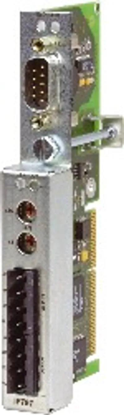
B&R 3IP161.60-1
2005 programmable I/O processor, 850 kB SRAM
- MPN
- 3IP161.60-1
Price and lead time confirmed within 1 business day
Request a Quote
- 1We check stock, condition and lead time
- 2You get a written quote by email
- 3Approve it and we ship — in-stock parts within 1 business day
- 12-month warranty (new) · 3-month (used/refurbished)
- 30-day returns, no restocking fee on unused parts
- 100% positive eBay feedback
- Ships via



What is the B&R 3IP161.60-1?
2005 programmable I/O processor, 850 kB SRAM, 1.5 MB FlashPROM, 1 RS232 interface, 1 CAN interface, CAN: Electrically isolated, network-capable, max. 12 digital inputs 24 VDC, sink, max. 12 digital outputs 24 VDC, 0.1 A, 6 analog inputs ±10 V, 14-bit, 6 analog outputs ±10 V, 12-bit, 2 outputs with +10 V and -10 V per terminal block, order 3x TB170 terminal blocks separately!
Specifications
General Information
| C-UL-US Listed | Yes |
| B&R ID Code | $34 |
| Module Type | B&R 2005 system module |
| Slot – ≥4 | Programmable I/O processor operation |
| Power Consumption – 5V | Max. 6.5 W |
| Power Consumption – 24 V | Max. 11.5 W, including potentiometer supply (if used externally) |
| Power Consumption – Total | Max. 18 W |
| Typical Instruction Cycle Time | 0.4 µs |
| Standard Memory – System RAM | 174 KB SRAM |
| Standard Memory – User RAM | 850 KB SRAM |
| Standard Memory – System PROM | 512 KB FlashPROM |
| Standard Memory – User PROM | 1.5 MB FlashPROM |
| Data Buffering – Backup Battery in 2005 Backplane | At least 4 years |
| Data Buffering – Buffering with AC240 Battery Module | At least 2 years |
| Data Buffering – Battery Monitoring | Yes, when operated as main CPU |
| Real-time Clock | Nonvolatile during CPU operation (buffered externally) |
| Resolution | 1s |
| Reset Button | Yes |
| Status display | 4 status LEDs, 4 interface LEDs |
Standard Communication Interfaces
| Application Interface IF1 | RS232 |
| Electrical Isolation | No |
| Design | 9-pin DSUB plug |
| Distance | Max. 15 m / 19200 Baud |
| Baud Rate | Max. 115.2 kBaud |
| Application Interface IF2 | CAN |
| Electrical Isolation | Yes |
| Design | 9-pin DSUB plug |
| Station number | Can be set using two node number switches |
| Distance | Max. 1,000 m |
| Maximum Baud Rate – Bus Length ≤60 m | 500 kBit/s |
| Maximum Baud Rate – Bus Length ≤200 m | 250 kBit/s |
| Maximum Baud Rate – Bus Length ≤1,000 m | 50 kBit/s |
| Application Interface IF3 | RS232 |
| Electrical Isolation | No |
| Design | 9-pin DSUB plug, the AC961 bus adapter is required for operation |
| Distance | Max. 15 m / 19200 Baud |
| Baud Rate | Max. 115.2 kBaud |
Static Characteristics
| Number and Type of Potentiometer | 2 outputs with +10 V and -10 V per terminal block |
| Electrical Isolation to PLC | Yes |
| Internal Reference Potential | AGND (analog ground for analog input circuit) |
| Output Current | ±80 mA (simultaneously) |
| Short Circuit Current | Typ. ±100 mA |
| Continuous Short Circuit Protection | Yes |
| Basic Accuracy – At 25° C | ±0.25% |
| Basic Accuracy – At 0 - 60° C | ±0.5% |
| Output Power | Max. 1.6 W |
Static Characteristics
| Input Type | Differential inputs for voltage measurement |
| Input Signal, Nominal | ±10 V |
| Maximum Continuous Overload (without damage) – Between +/- Connection | ±25 V |
| Maximum Continuous Overload (without damage) – Between Analog GND and + or - | ±30 V |
| Conversion Procedure | Successive approximation |
| Conversion Time | ≤100 µs for all 6 channels (parameters can be set by LTX functions in cyclic operating mode) |
| Digital Converter Resolution | 14-bit |
| Data Format in Application Program | INT |
| Value Range – Raw Values from ADC | $8320 - $7CE0 (typically) |
| Value Range – According to standard software using FUB IP161AIx (x ... 1 - | $8000 - $7FFC |
| Quantization | 1.22 mV per LSB |
| Overload – When range is exceeded (pos.) | $7FFF |
| Overload – When range is exceeded (neg.) | $8000 |
| Input Impedance in Signal Range – Static | 2 MΩ |
| Input Impedance in Signal Range – Dynamic | 3 kΩ/10 nF |
| Analog Input Measurement Error – Maximum Error at 25° C | ±0.06% |
| Temperature Coefficient – Offset Drift | ±0.00122%/°C |
| Temperature Coefficient – Gain Drift | ±0.00061%/°C |
| Linearization Method | Scaling conversion using software |
| Common Mode Voltage | ±5 V common mode voltage in contrast to other analog inputs |
| Wiring | Differential or potentiometer input |
| External Power Consumption | None (except potentiometer) |
| Protection | Internal clamp diodes protect against voltage spikes |
Dynamic Characteristics
| Input Filter – Characteristic | Low pass 1st order |
| Input Filter – Frequency Limit | 5 kHz |
| Total System Input Transfer Time | ≤100 µs for all 6 channels (parameters can be set) |
| Scan Duration (including response time) | 5 µs (response time on the multiplexer + sample time on the ADC) |
| Scan Repeat Time | Parameters can be set by LTX functions depending on the operating mode (cyclic, applications driven) |
| Minimum | 85 µs (cyclic operation) |
| Typical | 100 µs |
Operating Characteristics
| Operating Mode 1 | Fast analog value registering |
| Operating Mode 2 | Measurement values are recorded in FIFO memory |
| Operating Mode 3 | Comparator |
| Isolations Voltage between – Input and Bus | ±50 V |
| Isolations Voltage between – Inputs | 0 V (no electrical isolation) |
| Installation Recommendations | Double-sided twisted cable with 2-pin twisted Cu wires, max. 10 m, Under no circumstances should inputs and outputs be mixed in a multi-wire cable |
| Typical Example for External Connections | Differential input (+/- connection) Potentiometer input (- input pin should be connected with AGND) |
| Consequences of Incorrect Connection to the Input Terminals | Mixing up the +/- connections: negative result Open inputs: Overrun to $7FFF |
| Cross-talk between Inputs | >40 dB (DC - 60 Hz) |
| Non-Linearity | ±1 LSB (from ADC) |
| Continuity Without Missing Codes | No missing codes (in defined value range) |
| Calibrating or Testing for Maintaining the | No calibration or testing required |
Static Characteristics
| Number of Outputs | 6 voltage outputs ±10 V |
| Digital Converter Resolution | 12-bit |
| Data Format in Application Program | INT ($8000 - $7FF0) |
| Quantization | 1 LSB = 4.88 mV |
| Output Impedance in Signal Range | 0.25 Ω (2.5 mV at load change of 0 to 10 mA at 10 V) |
| Load Impedance | ≥1 kΩ |
| Alignment Precision at 25° C – Offset | ±0.0366% |
| Alignment Precision at 25° C – Total | ±0.4% |
| Temperature Coefficient – Offset Drift | ±0.00244%/°C |
| Temperature Coefficient – Gain Drift | ±0.00122%/°C |
Dynamic Characteristics
| Response Time When Changing Using | Max. 300 µs from 0.01% of end value (for resistive load) |
| Overshoot | For resistive load of 1 kΩ max. 3% |
| Output Response when Power Supply is | An enable relay is switched on at a defined value of 0 V |
| Switched On/Off | Default setting = short circuit on the output terminals using relay contact |
| Output Ripple Factor | ≤250 mVpp |
Operating Characteristics
| Operating Mode | Cyclic output with approx. 10 kHz |
| Isolation Voltages between Output and | ±50 V |
| Installation Recommendations | Double-sided twisted cable with 2-pin twisted Cu wires, max. 10 m, Under no circumstances should inputs and outputs be mixed in a multi-wire cable |
| Calibrating or Testing for Maintaining the | No calibration or testing required |
| Permitted Load Types | Resistive, inductive |
| Maximum Capacitive Load | ≤100 nF (larger capacity extends the response time) |
| Typical Example for External Connections | e.g. analog hydraulic valve |
| Consequences of Incorrect Connection to the Output Terminals | Depends on wiring and voltage size (in worst case scenario all 6 output circuits become defective) |
| Continuity | ±0.5 LSB (DAC value) |
| Non-Linearity | Max. ±4 LSB (DAC value) |
| Repeat Precision at a Certain | ±2 LSB |
| Temperature after a Specified Stabilizing | (noise at constant temperature in 24 hours) |
Static Characteristics
| Number of Inputs | Up to 12 Configuration as input or output takes place in groups of two using software |
| Maximum Peak Voltage | +35 V |
| Rated Voltage | +24 VDC |
| Rated Frequency | Max. 200 kHz (symmetrical square wave) |
| Wiring | Sink |
| Limit Values – 0-Signal UL | ≤5 V |
| Limit Values – 0-Signal IL | ≤2 mA |
| Limit Values – 1-Signal UH | ≥11 V |
| Limit Values – 1-Signal IH | ≥5 mA |
| Delay 0 to 1 | ≤2.5 µs |
| Delay 1 to 0 | ≤2.5 µs |
| Power Consumption (external) – Per Group at 24 V (no load) | ≤0.48 W |
| Power Consumption (external) – Per Digital Input at 24 V | 0.24 W |
Additional Characteristics
| Status Display | No |
| Interrupt Capable | Yes Parameters can be set using LTX functions - each digital input can trigger an IRQ WARNING: Handling takes place using an exception task |
Operating Characteristics
| Consequences of Incorrect Input | At 24 V and COM exchange: internal reverse polarity diode |
| Connections | For active inputs without supply: Output driver is not protected |
| Isolations Voltage between – Input and Bus | ±50 V |
| Isolations Voltage between – Inputs | Digital group <-> Digital group: ±50 V |
| Consequences of Removing/Inserting | Must not be removed/inserted during operation (= system module) |
| Additional Exterior Load when Inputs and | No load required (push/pull) |
| Explanation of Signal Evaluation | Each digital input is assigned a TPU pin, different types of signal evaluation are possible (edges triggering, counter input) depending on the TPU function, several inputs can be combined (e.g. incremental encoder) |
| Recommended Length for Cable and | The recommended cable length and cable type depends |
| Connections Depending on Cable Type and Electromagnetic Compatibility | on the maximum frequency of use,Shielded cable are recommended for fast signals (>10 kHz) |
| Typical Example for External Connections | Only sink connection |
| Different Circuits Possible | Each group is electrically isolated |
Static Characteristics
| Number and Type of Outputs | Up to 12 transistor outputs (Push/Pull) Configuration as input or output takes place in groups of two using software |
| Maximum Switching Voltage | +35 V |
| Maximum Peak Voltage | +50 V |
| Rated Current (1-Signal) | ±100 mA |
| Rated Voltage | +24 VDC |
| Switching Voltage Range | +12 VDC to +35 VDC |
| Rated Frequency | Max. 100 kHz |
| Current Range at 1-Signal (continuous at maximum voltage) | ±100 mA |
| Voltage Drop (1-Signal), Internal | ∆U at 100 mA is ≤1 V |
| Resistance – Protected and short circuit outputs | IK ≤300 mA, continuous |
| Short Circuit Current | 110 to 300 mA |
| Turn-off delay | 100 µs |
| Over-Temperature Cutoff | ≥ 170° C |
| Wiring | Sink or source |
| Power Consumption per Group (external) | ≤20 mA + load current for the outputs |
Additional Characteristics
| Status Display | No |
Protection Characteristics
| For Protected Outputs: | Internal current limitation from ±110 mA to ±300 mA |
| For Short Circuit Proof Outputs: | Internal thermal overload protection and internal current limitation |
| For Non-Protected Outputs: | No prescribed protective circuit |
| Characteristics of the Output Circuit | Internal clamping diodes for group supply voltage |
| Protection Against Voltage Spikes when | Short term current of ±1 A, duration ≤10 ms |
| Type of External Protective Circuit | For inductive loads, clamping diodes can also be connected between the output and the group supply (24 VDC and GND) |
Dynamic Characteristics
| Delay 0 to 1 | ≤2 µs for resistive loads |
| Delay 1 to 0 | ≤2 µs for resistive loads |
| Switch Frequency with Resistive Load | 100 kHz with resistive load |
Operating Characteristics
| Consequences when Outputs Incorrectly | Depending on the error, the worst case scenario could cause |
| Connected | destruction of digital group |
| Consequences of Multiple Overloads on | The entire group is switched off due to internal thermal monitoring |
| Output Behavior when the Controller Falls | Output switched to high resistance |
| Total Output Current | Max. 400 mA/group (static) |
| Isolation Voltages between Output and | ±50 V |
| Recommended Procedure when | Must not be removed/inserted during operation (= system module) |
| Typical Example for External Connections | Sink or source wiring |
Mechanical Characteristics
| Dimensions | B&R 2005 double-width |
No matching specifications
Accessories
Required accessories (order separately)
| 3TB170.91 | Terminal blocks — 2005 terminal block, 20-pin, push-in terminal block |
| 3TB170.9 | Terminal blocks — 2005 terminal block, 20-pin, screw clamp terminal block |
Optional accessories (4)
| 7AC911.9 | Infrastructure components — The AC911 bus connector is used to connect a controller to a CAN network. The terminating resistor is integrated in the bus connector. The… |
| 0AC913.92 | Infrastructure components — Bus adapter, CAN, 2 CAN interfaces, including 30 cm attachment cable (DSUB) |
| 0AC912.9 | Infrastructure components — Bus adapter, CAN, 1 CAN interface |
| 0AC961.9 | Undefined — Accessory bus adapter (CAN, RS232) |
Downloads & documentation
Official documents from B&R, downloaded directly from the manufacturer.
Data sheets & manuals
3IP161.60-1: frequently asked questions
When can 3IP161.60-1 be shipped?
3IP161.60-1 is sourced on request — request a quote and we'll confirm the exact availability and shipping timeline for this specific unit.
Can I pick up 3IP161.60-1 in person?
Local pickup from our Groningen, Netherlands warehouse may be possible — contact us before ordering to check availability and arrange a collection time.
Is express delivery available?
Yes — mention it when you request a quote for 3IP161.60-1 and we'll include express shipping options in our reply.
My factory is down and I need this urgently — can you help?
For a critical breakdown, contact us directly at +31 (0)50-7110348 or sales@partnerplc.com — we can look into same-day courier or dedicated taxi/hotshot delivery for 3IP161.60-1, subject to availability and destination.
More B&R parts
B&R 3IP161.60-1Price and lead time confirmed within 1 business day
Request a Quote