
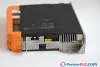
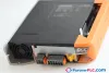

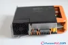
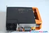

B&R 8EI4X5MWS10.0600-1 Used Rev. C0 – ACOPOS P3 servo drive, 1 digital multi-standard encoder…
Request a Quote



Quick facts
| Availability | In stock — 1 available |
| Category | Servo & Motion Control |
| Warranty | 3-month |
| Weight | 3.2 kg |
| Country of origin | AT |
Shipping & availability
When can 8EI4X5MWS10.0600-1 be shipped?
8EI4X5MWS10.0600-1 is in stock and typically ships within 1 business day via UPS, DHL or FedEx, worldwide.
Can I pick up 8EI4X5MWS10.0600-1 in person?
Local pickup from our Groningen, Netherlands warehouse may be possible — contact us before ordering to check availability and arrange a collection time.
Is express delivery available?
Yes — alongside standard UPS, DHL and FedEx shipping, express (next-day) delivery is available at checkout for in-stock items like 8EI4X5MWS10.0600-1.
My factory is down and I need this urgently — can you help?
For a critical breakdown, contact us directly at +31 (0)50-7110348 or sales@partnerplc.com — we can look into same-day courier or dedicated taxi/hotshot delivery for 8EI4X5MWS10.0600-1, subject to availability and destination.
ACOPOS P3 servo drive, 1 digital multi-standard encoder interface per axis, 3x 200-230 VAC, 1x 110-230 VAC, 4.5 A, 1 axis, wall mounting, 1-row connector set, cover, integrated braking resistor
Specifications
General information
| Support – Dynamic node allocation (DNA) | Yes |
| Slots for plug-in modules | 1 |
Mains connection
| Network configurations | TN-S, TN-C-S with grounded neutral |
| Mains input voltage | 1x 110 VAC to 230 VAC ±10%; 3x 200 VAC to 230 VAC ±10% |
| Frequency | 50 / 60 Hz ±4% |
| Installed load | Max. 2.5 kVA |
| Inrush current | Max. 22 A |
| Switch-on interval | Typ. 60 s |
| Integrated line filter per EN 61800-3, category C3 | No " data-placement="top" data-html="true" data-container="body" data-content="A line filter must be connected.<br>CE compliance can only be ensured by connecting an upstream B&R line filter (e.g. 8B0F0160H000.A00-1).<br>In extreme cases, using line filters from 3rd-party manufacturers can result in irreparable damage to the ACOPOS P3 8EI servo drive."> |
| Power dissipation at device nominal power without braking resistor | [(30 + 10 * P AVG [kW] + 5.8 * I AX1 [A] + 0.25 * I BR1 2 [A]) + P VSLOT ) * 1.1] [W] " data-placement="top" data-html="true" data-container="body" data-content="P<sub>AVG</sub> ... Average continuous power of the module <br>I<sub>AX1</sub> ... RMS value of the current on axis 1 <br>I<sub>BR1</sub> ... Nominal current of the motor holding brake for axis 1 <br>P<sub>VSLOT</sub> ... Power dissipation of the 8EAC plug-in module"> |
DC bus connection
| DC bus capacitance | 1880 µF |
24 VDC power supply
| Input voltage | 24 VDC ±25% |
| Input capacitance | 4312 µF |
| Current consumption | 0.9 A + Current for motor holding brake " data-placement="top" data-html="true" data-container="body" data-content="Current consumption depends on the respective configuration of the ACOPOS P3 8EI servo drive."> |
Motor connection
| Reduction of continuous current depending on switching frequency " data-placement="top" data-html="true" data-container="body" data-content="The temperature specifications refer to the ambient temperature."> – Switching frequency 5 kHz | No reduction " data-placement="top" data-html="true" data-container="body" data-content="Value for the nominal switching frequency."> |
| Reduction of continuous current depending on switching frequency " data-placement="top" data-html="true" data-container="body" data-content="The temperature specifications refer to the ambient temperature."> – Switching frequency 10 kHz | No reduction |
| Reduction of continuous current depending on switching frequency " data-placement="top" data-html="true" data-container="body" data-content="The temperature specifications refer to the ambient temperature."> – Switching frequency 20 kHz | No reduction " data-placement="top" data-html="true" data-container="body" data-content="The module cannot supply the full continuous current at this switching frequency. This unusual value for the ambient temperature, at which derating of the continuous current must be taken into account, ensures that the derating of the continuous current can be determined in the same manner as at other switching frequencies."> |
| Reduction of continuous current depending on installation elevation – Starting at 500 m above sea level | 0.45 A eff per 1000 m |
| Protective measures – Overload protection | Yes |
| Protective measures – Short-circuit and ground fault protection | Yes |
| Variant – U, V, W, PE | Connector |
| Variant – Shield connection | Yes |
| Terminal connection cross section – With wire end sleeve | 1.5 to 6 mm² |
| Terminal connection cross section – UL/C-UL-US | 24 to 8 AWG |
| Terminal connection cross section – CSA | 24 to 8 AWG |
| Max. motor line length depending on switching frequency – Switching frequency 5 kHz | 75 m " data-placement="top" data-html="true" data-container="body" data-content="The sum of the cable lengths of all motor cables connected to this module is not permitted to exceed this value."> |
| Max. motor line length depending on switching frequency – Switching frequency 10 kHz | 37.5 m " data-placement="top" data-html="true" data-container="body" data-content="The sum of the cable lengths of all motor cables connected to this module is not permitted to exceed this value."> |
| Max. motor line length depending on switching frequency – Switching frequency 20 kHz | 18.75 m " data-placement="top" data-html="true" data-container="body" data-content="The sum of the cable lengths of all motor cables connected to this module is not permitted to exceed this value."> |
| Quantity | 1 |
| Continuous power per motor connection " data-placement="top" data-html="true" data-container="body" data-content="Valid under the following conditions: 325 VDC DC bus voltage, 5 kHz switching frequency, 40°C ambient temperature, installation elevation <500 m above sea level, no derating due to cooling type."> | 1 kW |
| Continuous current per motor connection " data-placement="top" data-html="true" data-container="body" data-content="Valid under the following conditions: 325 VDC DC bus voltage, 5 kHz switching frequency, 40°C ambient temperature, installation elevation <500 m above sea level, no derating due to cooling type."> | 4.5 A eff |
| Peak current per motor connection | 12.25 A eff |
| Peak power output | 2.5 kW |
| Nominal switching frequency | 5 kHz |
| Possible switching frequencies " data-placement="top" data-html="true" data-container="body" data-content="B&R recommends operating the module at its nominal switching frequency. Operating the module at a higher switching frequency for application-specific reasons reduces the continuous current and increases CPU utilization."> | 5 / 10 / 20 kHz |
| Insulation stress of the connected motor per IEC TS 60034-25:2004 | Limit value curve A |
| Max. output frequency | 598 Hz " data-placement="top" data-html="true" data-container="body" data-content="The module's electrical output frequency (SCTRL_SPEED_ACT * MOTOR_POLEPAIRS) is monitored to protect against dual use in accordance with Regulation (EC) 428/2009 | 3A225. If the electrical output frequency of the module exceeds the limit value of 598 Hz uninterrupted for more than 0.5 s, then the current movement is aborted and error 6060 is output ("Power unit: Limit speed exceeded")."> |
Motor holding brake connection
| Protective measures – Overload and short-circuit protection | Yes |
| Protective measures – Open-circuit monitoring | Yes |
| Protective measures – Undervoltage monitoring | Yes |
| Quantity | 1 |
| Output voltage " data-placement="top" data-html="true" data-container="body" data-content="During configuration, it is necessary to check if the minimum voltage can be maintained on the holding brake with the specified input voltage and wiring. For the operating voltage range of the holding brake, see the user documentation for the motor being used."> | Depends on the input voltage on connector X2 |
| Continuous current per connection | 1.3 A |
| Max. internal resistance | 0.25 Ω |
| Extinction potential | Approx. 30 V |
| Max. extinction energy per switching operation | 1.5 Ws |
| Max. switching frequency | 0.5 Hz |
| Response threshold for open-circuit monitoring | Approx. 30 mA |
Braking resistor " data-placement="top" data-html="true" data-container="body" data-content="There is a connection for external braking resistors. An internal braking resistor is available as an option.">
| Peak power int./ext. | 1.5 kW / 11 kW |
| Continuous power int./ext. | 100 W / 970 W |
| Minimum braking resistance (ext.) | 12 Ω |
Enable inputs
| Electrical isolation – Input - ACOPOS P3 | Yes |
| Electrical isolation – Input - Input | Yes |
| Input voltage – Nominal | 24 VDC |
| Input voltage – Maximum | 30 VDC |
| Switching threshold – Low | <5 V |
| Switching threshold – High | >15 V |
| Switching delay at nominal input voltage – Enable 1 → 0, PWM off | 2 ms |
| Switching delay at nominal input voltage – Enable 0 → 1, ready for PWM | 0.3 ms |
| Quantity | 2 |
| Circuit | Sink |
| Input current at nominal voltage | Approx. 9 mA |
| Modulation compared to ground potential | Max. ±38 V |
| OSSD signal connections " data-placement="top" data-html="true" data-container="body" data-content="OSSD (output signal switching device) signals are used to monitor signal lines for short circuits and cross faults."> | 0.5 ms |
Encoder interfaces
| Electrical isolation – Encoder - ACOPOS P3 | No |
| Encoder power supply – Short-circuit proof | Yes |
| Encoder power supply – Overload-proof | Yes |
| Encoder power supply – Output voltage | Typ. 11.4 V |
| Encoder power supply – Load capacity | 300 mA |
| Synchronous serial interface – Signal transmission | RS485 |
| Synchronous serial interface – Data transfer rate | 6.25 Mbit/s |
| Quantity | 1 |
| Type | EnDat 2.2 |
| Connections | 8-pin female Mini I/O connector |
| Status indicators | None " data-placement="top" data-html="true" data-container="body" data-content="The direction of rotation of the encoder can be displayed on the 8EAD0000.000-1 display module."> |
| Encoder monitoring | No |
| Max. encoder cable length | 100 m ; Depends on the cross section of the power supply wires in the encoder cable " data-placement="top" data-html="true" data-container="body" data-content="Maximum encoder cable length l<sub>max</sub> can be calculated as follows (the maximum permissible encoder cable length of 100 m is not permitted to be exceeded): <br><br>l<sub>max</sub> = 7.9 / I<sub>G</sub> * A * 1/(2*ρ) <br><br>I<sub>G</sub> ... Max. current consumption of the encoder [A]. <br>A ... Cross section of the power supply wires [mm²] <br>ρ ... Specific resistance [Ω mm²/m] (e.g. for copper: ρ = 0.0178)"> |
| Max. power consumption per encoder interface | P ENCODER [W] = U 24V [V] * (I ENCODER [A] * 0.7) + 0.5 W " data-placement="top" data-html="true" data-container="body" data-content="I<sub>ENCODER</sub> ... Current consumption of the encoder<br>U<sub>24V</sub> ... Input voltage on the +24 VDC input of the module"> |
Trigger inputs
| Electrical isolation – Input - ACOPOS P3 | Yes |
| Electrical isolation – Input - Input | Yes |
| Input voltage – Nominal | 24 VDC |
| Input voltage – Maximum | 30 VDC |
| Switching threshold – Low | <5 V |
| Switching threshold – High | >15 V |
| Switching delay – Rising edge | <2 µs |
| Switching delay – Falling edge | <1 µs |
| Quantity | 2 |
| Circuit | Sink |
| Input current at nominal voltage | Approx. 4 mA |
| Modulation compared to ground potential | Max. ±38 V |
Temperature sensor connection
| Quantity | 1 |
| Resistance range | 500 Ω to 5 kΩ |
Support
| Software – ACP10 | V3.13.0 |
Operating conditions
| Permissible mounting orientations – Hanging vertically | Yes |
| Permissible mounting orientations – Standing horizontally | In preparation |
| Installation elevation above sea level – Nominal | 0 to 500 m |
| Installation elevation above sea level – Maximum | 4000 m |
| Pollution degree per EN 61800-5-1 | 2 (non-conductive pollution) |
| Overvoltage category per EN 61800-5-1 | III |
| Degree of protection per EN 60529 | IP20 |
Ambient conditions
| Temperature – Nominal | 5 to 40°C |
| Temperature – Maximum | 55°C |
| Temperature – Storage | -25 to 55°C |
| Temperature – Transport | -25 to 70°C |
| Relative humidity – Operation | 5 to 85%, non-condensing |
| Relative humidity – Storage | 5 to 95% |
| Relative humidity – Transport | 95% at 40°C |
Mechanical properties
| Dimensions – Wall mounting | 258.5 mm (with 8EXA front cover: 261 mm) |
| Dimensions – Width | 66 mm |
| Dimensions – Height | 290 mm |
| Weight | 3.2 kg |
Downloads & documentation
Official documents from B&R, downloaded directly from the manufacturer.
Data sheets & manuals
| Datasheet 8EI4X5MWS10.XXXX-1 | PDF · 948 KB · 1.7 (03/10/2022) - EN |
| ACOPOS P3 User´s Manual | PDF · 178 MB · 1.40 (06/16/2025) - EN |
Certificates (1)
| E225616 UL Certificate of Compliance ACOPOS P3 | PDF · 241 KB · 1.2 (09/11/2019) |
More B&R parts
 UsedB&R 5C5601.12 Used Rev. K0 – Provit 5600 Controller system unit for Intel Celeron and…
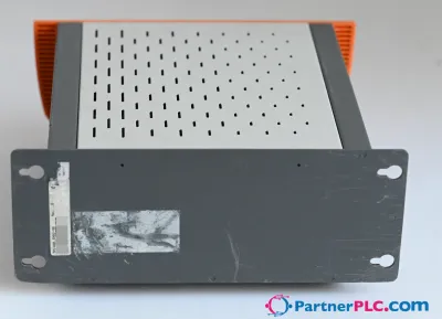 UsedB&R 5PC600.SX02-00 Used Rev. D0 – APC620 system unit 2 PCI slots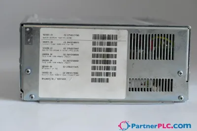
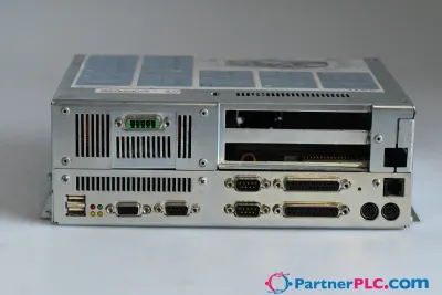
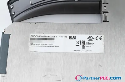 UsedB&R 8B0C0320HW00.002-1 Used Rev. H0 – Connections for supplying external 24 V devices
 UsedB&R 7BP708.0 Used Rev. 10.00 – 2003 module rack for 8 modules
 UsedB&R 7BP705.0 Used Rev. 10.00 – 2003 module rack for 5 modules