























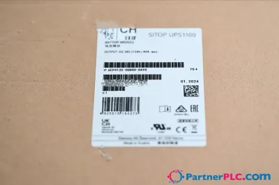
 New
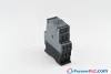
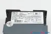
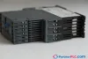

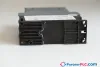

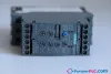
SiemensUsed
Siemens 3RW4026-1BB14
Circuit Protection & Switching
- MPN
- 3RW4026-1BB14
- Category
- Circuit Protection & Switching
€174.90excl. VAT & shipping
In stock — 1 available·Ships within 1 business day
Need a larger quantity or a formal quote?
Request a Quote
- 3-month warranty
- 30-day returns, no restocking fee on unused parts
- 100% positive eBay feedback
- Ships via



What is the Siemens 3RW4026-1BB14?
Circuit Protection & Switching
Specifications
General technical data
| Technical Product Detail Page | https://i.siemens.com/1P3RW4026-1BB14 |
| product brand name | SIRIUS |
| product designation | Soft starter |
| product feature — integrated bypass contact system | Yes |
| product feature — thyristors | Yes |
| product function — intrinsic device protection | Yes |
| product function — motor overload protection | Yes |
| product function — evaluation of thermistor motor protection | No |
| product function — external reset | Yes |
| product function — adjustable current limitation | Yes |
| product function — inside-delta circuit | No |
| product component motor brake output | No |
| insulation voltage rated value | 600 V |
| degree of pollution | 3, acc. to IEC 60947-4-2 |
| blocking voltage of the thyristor maximum | 1 600 V |
| reference code according to EN 61346-2 | Q |
| reference code according to DIN 40719 extended according to IEC 204-2 according to IEC 750 | G |
Power Electronics
| operational current — at 40 °C rated value | 25 A |
| operational current — at 50 °C rated value | 23 A |
| operational current — at 60 °C rated value | 21 A |
| — at standard circuit at 40 °C rated value | 5.5 kW |
| — at standard circuit at 40 °C rated value | 11 kW |
| yielded mechanical performance [hp] for 3-phase AC motor at 200/208 V at standard circuit at 50 °C rated value | 5 hp |
| operating frequency rated value | 50 ... 60 Hz |
| relative negative tolerance of the operating frequency | -10 % |
| relative positive tolerance of the operating frequency | 10 % |
| operating voltage at standard circuit rated value | 200 ... 480 V |
| relative negative tolerance of the operating voltage at standard circuit | -15 % |
| relative positive tolerance of the operating voltage at standard circuit | 10 % |
| minimum load [%] | 20 % |
| adjustable motor current for motor overload protection minimum rated value | 10 A |
| continuous operating current [% of Ie] at 40 °C | 115 % |
| power loss [W] at operational current at 40 °C during operation typical | 8 W |
Control circuit/ Control
| type of voltage of the control supply voltage | AC/DC |
| control supply voltage frequency 1 rated value | 50 Hz |
| control supply voltage frequency 2 rated value | 60 Hz |
| relative negative tolerance of the control supply voltage frequency | -10 % |
| relative positive tolerance of the control supply voltage frequency | 10 % |
| control supply voltage 1 at AC at 50 Hz | 110 ... 230 V |
| control supply voltage 1 at AC at 60 Hz | 110 ... 230 V |
| relative negative tolerance of the control supply voltage at AC at 50 Hz | -15 % |
| relative positive tolerance of the control supply voltage at AC at 50 Hz | 10 % |
| relative negative tolerance of the control supply voltage at AC at 60 Hz | -15 % |
| relative positive tolerance of the control supply voltage at AC at 60 Hz | 10 % |
| control supply voltage 1 at DC | 110 ... 230 V |
| relative negative tolerance of the control supply voltage at DC | -15 % |
| relative positive tolerance of the control supply voltage at DC | 10 % |
| display version for fault signal | red |
Mechanical data
| size of engine control device | S0 |
| width | 45 mm |
| height | 125 mm |
| depth | 155 mm |
| fastening method | screw and snap-on mounting |
| mounting position | With additional fan: With vertical mounting surface +/-90° rotatable, with vertical mounting surface +/- 22.5° tiltable to the front and back Without additional fan: With vertical mounting surface +/-10° rotatable, with vertical mounting surface +/- 10° t |
| required spacing with side-by-side mounting — upwards | 60 mm |
| required spacing with side-by-side mounting — at the side | 15 mm |
| required spacing with side-by-side mounting — downwards | 40 mm |
| wire length maximum | 300 m |
| number of poles for main current circuit | 3 |
Connections/ Terminals
| type of electrical connection — for main current circuit | screw-type terminals |
| type of electrical connection — for auxiliary and control circuit | screw-type terminals |
| number of NC contacts for auxiliary contacts | 0 |
| number of NO contacts for auxiliary contacts | 2 |
| number of CO contacts for auxiliary contacts | 1 |
| type of connectable conductor cross-sections for main contacts for box terminal using the front clamping point — solid | 2x (1 ... 2.5 mm²), 2x (2.5 ... 6 mm²), max. 1x 10 mm² |
| type of connectable conductor cross-sections for main contacts for box terminal using the front clamping point — finely stranded with core end processing | 2x (1 ... 2.5 mm²), 2x (2.5 ... 6 mm²) |
| type of connectable conductor cross-sections for AWG cables for main contacts for box terminal — using the front clamping point | 1x 8, 2x (16 ... 10) |
| type of connectable conductor cross-sections for auxiliary contacts — solid | 2x (0.5 ... 2.5 mm²) |
| type of connectable conductor cross-sections for auxiliary contacts — finely stranded with core end processing | 2x (0.5 ... 1.5 mm²) |
| type of connectable conductor cross-sections for AWG cables — for auxiliary contacts | 2x (20 ... 14) |
| type of connectable conductor cross-sections for AWG cables — for auxiliary contacts finely stranded with core end processing | 2x (20 ... 16) |
Ambient conditions
| installation altitude at height above sea level | 5 000 m |
| environmental category — during transport according to IEC 60721 | 2K2, 2C1, 2S1, 2M2 (max. fall height 0.3 m) |
| environmental category — during storage according to IEC 60721 | 1K6 (only occasional condensation), 1C2 (no salt mist), 1S2 (sand must not get inside the devices), 1M4 |
| environmental category — during operation according to IEC 60721 | 3K6 (no formation of ice, no condensation), 3C3 (no salt mist), 3S2 (sand must not get into the devices), 3M6 |
| ambient temperature — during operation | -25 ... +60 °C |
| ambient temperature — during storage | -40 ... +80 °C |
| derating temperature | 40 °C |
| protection class IP on the front according to IEC 60529 | IP20 |
| touch protection on the front according to IEC 60529 | finger-safe, for vertical contact from the front |
UL/CSA ratings
| — at standard circuit at 50 °C rated value | 5 hp |
| — at standard circuit at 50 °C rated value | 15 hp |
| contact rating of auxiliary contacts according to UL | B300 / R300 |
No matching specifications
Downloads & documentation
Official documents from Siemens, downloaded directly from the manufacturer.
Data sheets & manuals
3RW4026-1BB14: frequently asked questions
When can 3RW4026-1BB14 be shipped?
3RW4026-1BB14 is in stock and typically ships within 1 business day via UPS, DHL or FedEx, worldwide.
Can I pick up 3RW4026-1BB14 in person?
Local pickup from our Groningen, Netherlands warehouse may be possible — contact us before ordering to check availability and arrange a collection time.
Is express delivery available?
Yes — alongside standard UPS, DHL and FedEx shipping, express (next-day) delivery is available at checkout for in-stock items like 3RW4026-1BB14.
My factory is down and I need this urgently — can you help?
For a critical breakdown, contact us directly at +31 (0)50-7110348 or sales@partnerplc.com — we can look into same-day courier or dedicated taxi/hotshot delivery for 3RW4026-1BB14, subject to availability and destination.
More Siemens parts
New New
 New
 New
Siemens 3RW4026-1BB14€174.90
Buy Now