

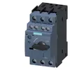
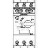
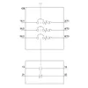
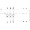
Siemens 3RV2021-4PA15-Z X95 – Circuit breaker size S0 for motor protection
Request a Quote



Quick facts
| Availability | Confirmed on request |
| Category | SIRIUS 3RV2 motor starter protectors |
| Lifecycle | Active |
| Warranty | 12-month (new) · 3-month (used/refurbished) |
| Weight | 0.4 kg |
| Datasheet | Manufacturer datasheet ↗ |
Shipping & availability
When can 3RV2021-4PA15-Z X95 be shipped?
3RV2021-4PA15-Z X95 is sourced on request — request a quote and we'll confirm the exact availability and shipping timeline for this specific unit.
Can I pick up 3RV2021-4PA15-Z X95 in person?
Local pickup from our Groningen, Netherlands warehouse may be possible — contact us before ordering to check availability and arrange a collection time.
Is express delivery available?
Yes — mention it when you request a quote for 3RV2021-4PA15-Z X95 and we'll include express shipping options in our reply.
My factory is down and I need this urgently — can you help?
For a critical breakdown, contact us directly at +31 (0)50-7110348 or sales@partnerplc.com — we can look into same-day courier or dedicated taxi/hotshot delivery for 3RV2021-4PA15-Z X95, subject to availability and destination.
Circuit breaker size S0 for motor protection, CLASS 10 A-release 30...36 A N-release 432 A screw terminal Standard switching capacity with transverse auxiliary switches 1 NO+1 NC Reusable packaging Pack = 43 units
Specifications
General
| product brand name | SIRIUS |
| product designation | Circuit breaker |
| design of the product | For motor protection |
| product type designation | 3RV2 |
General technical data
| Product equipment of circuit breaker for motor protection complete unit with protection device | Yes |
| size of the circuit-breaker | S0 |
| size of contactor can be combined company-specific | S00, S0 |
| product function disconnector functionality | Yes |
| product extension auxiliary switch | Yes |
| power loss [W] for rated value of the current — at AC in hot operating state | 16.25 W |
| power loss [W] for rated value of the current — at AC in hot operating state per pole | 5.4 W |
| type of calculation of power loss current-dependent | quadratic |
| insulation voltage with degree of pollution 3 at AC rated value | 690 V |
| surge voltage resistance rated value | 6 kV |
| maximum permissible voltage for protective separation — in networks with ungrounded star point between main and auxiliary circuit | 400 V |
| maximum permissible voltage for protective separation — in networks with grounded star point between main and auxiliary circuit | 400 V |
| protection class IP — on the front according to IEC 60529 | IP20 |
| protection class IP — on the front | IP20 |
| protection class IP — of the terminal | IP20 |
| shock resistance according to IEC 60068-2-27 | 25g / 11 ms |
| mechanical service life (operating cycles) — of the main contacts typical | 100 000 |
| mechanical service life (operating cycles) — of auxiliary contacts typical | 100 000 |
| electrical endurance (operating cycles) typical | 100 000 |
| reference code according to IEC 81346-2 | Q |
| continuous current rated value | 36 A |
| Substance Prohibitance (day/month/year) | 10/01/2009 |
| Net Weight | 376.18 g |
Ambient conditions
| installation altitude at height above sea level maximum | 2 000 m |
| ambient temperature — during operation | -20 ... +40 °C |
| ambient temperature — during storage | -50 ... +80 °C |
| ambient temperature — during transport | -50 ... +80 °C |
| temperature compensation | -20 ... +60 °C |
| relative humidity during operation | 10 ... 95 % |
Main circuit
| number of poles for main current circuit | 3 |
| adjustable current response value current of the current-dependent overload release | 30 ... 36 A |
| type of voltage for main current circuit | AC |
| operating voltage — rated value | 690 V |
| operating voltage — rated value | 20 ... 690 V |
| operating voltage — at AC-3 rated value maximum | 690 V |
| operating frequency rated value | 50 ... 60 Hz |
| operational current rated value | 36 A |
| operational current — at AC-3 at 400 V rated value | 36 A |
| operating power — at AC-3 — at 230 V rated value | 7.5 kW |
| operating power — at AC-3 — at 400 V rated value | 18.5 kW |
| operating power — at AC-3 — at 500 V rated value | 22 kW |
| operating power — at AC-3 — at 690 V rated value | 30 kW |
| operating frequency — at AC-3 maximum | 15 1/h |
Auxiliary circuit
| design of the auxiliary switch | transverse |
| type of voltage for auxiliary and control circuit | AC/DC |
| number of NC contacts for auxiliary contacts | 1 |
| number of NO contacts for auxiliary contacts | 1 |
| number of CO contacts for auxiliary contacts | 0 |
| operational current of auxiliary contacts at AC-15 — at 24 V | 2 A |
| operational current of auxiliary contacts at AC-15 — at 120 V | 0.5 A |
| operational current of auxiliary contacts at AC-15 — at 125 V | 0.5 A |
| operational current of auxiliary contacts at AC-15 — at 230 V | 0.5 A |
| operational current of auxiliary contacts at DC-13 — at 24 V | 1 A |
| operational current of auxiliary contacts at DC-13 — at 60 V | 0.15 A |
Protective and monitoring functions
| product function — ground fault detection | No |
| product function — phase failure detection | Yes |
| trip class | CLASS 10 |
| design of the overload release | thermal |
| protection function thermal overload protection (ANSI 49) | Yes |
| maximum short-circuit current breaking capacity (Icu) — at AC at 240 V rated value | 100 kA |
| maximum short-circuit current breaking capacity (Icu) — at AC at 400 V rated value | 20 kA |
| maximum short-circuit current breaking capacity (Icu) — at AC at 500 V rated value | 6 kA |
| maximum short-circuit current breaking capacity (Icu) — at AC at 690 V rated value | 3 kA |
| operating short-circuit current breaking capacity (Ics) at AC — at 240 V rated value | 100 kA |
| operating short-circuit current breaking capacity (Ics) at AC — at 400 V rated value | 10 kA |
| operating short-circuit current breaking capacity (Ics) at AC — at 500 V rated value | 3 kA |
| operating short-circuit current breaking capacity (Ics) at AC — at 690 V rated value | 2 kA |
| response value current of instantaneous short-circuit trip unit | 432 A |
UL/CSA ratings
| full-load current (FLA) for 3-phase AC motor — at 480 V rated value | 36 A |
| full-load current (FLA) for 3-phase AC motor — at 600 V rated value | 36 A |
| yielded mechanical performance [hp] — for single-phase AC motor — at 110/120 V rated value | 3 hp |
| yielded mechanical performance [hp] — for single-phase AC motor — at 230 V rated value | 5 hp |
| yielded mechanical performance [hp] — for 3-phase AC motor — at 200/208 V rated value | 10 hp |
| yielded mechanical performance [hp] — for 3-phase AC motor — at 220/230 V rated value | 10 hp |
| yielded mechanical performance [hp] — for 3-phase AC motor — at 460/480 V rated value | 25 hp |
| contact rating of auxiliary contacts according to UL | C300 / R300 |
| UL File Number (CCN) | E47705 (NLRV, NLRV7) |
Short-circuit protection
| product function short circuit protection | Yes |
| design of the short-circuit trip | magnetic |
| design of the fuse link — for short-circuit protection of the auxiliary switch required | Fuse gL/gG: 10 A, miniature circuit breaker C 6 A (short-circuit current Ik < 400 A) |
| design of the fuse link for IT network for short-circuit protection of the main circuit — at 400 V | gG 63 A |
| design of the fuse link for IT network for short-circuit protection of the main circuit — at 500 V | gG 63 A |
| design of the fuse link for IT network for short-circuit protection of the main circuit — at 690 V | gG 63 A |
| certificate of suitability according to ATEX directive 2014/34/EU | DMT 02 ATEX F 001 |
| type of protection according to ATEX directive 2014/34/EU | Ex II (2) GD |
Installation/ mounting/ dimensions
| mounting position | any |
| fastening method | screw and snap-on mounting onto 35 mm DIN rail according to DIN EN 60715 |
| Mounting method of circuit breaker for Transformer protection, Generator protection and system protection optional standard bar mounting | Yes |
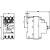
| height | 97 mm |
| width | 45 mm |
| depth | 97 mm |
| required spacing — with side-by-side mounting — forwards | 0 mm |
| required spacing — with side-by-side mounting — backwards | 0 mm |
| required spacing — with side-by-side mounting — upwards | 70 mm |
| required spacing — with side-by-side mounting — downwards | 70 mm |
| required spacing — with side-by-side mounting — at the side | 9 mm |
| required spacing — for grounded parts — forwards | 0 mm |
| required spacing — for grounded parts — backwards | 0 mm |
| required spacing — for grounded parts — upwards | 70 mm |
| required spacing — for grounded parts — at the side | 30 mm |
| required spacing — for grounded parts — downwards | 70 mm |
| required spacing — for live parts — forwards | 0 mm |
| required spacing — for live parts — backwards | 0 mm |
| required spacing — for live parts — upwards | 70 mm |
| required spacing — for live parts — downwards | 70 mm |
| required spacing — for live parts — at the side | 30 mm |
| required spacing — for grounded parts at 400 V — downwards | 30 mm |
| required spacing — for grounded parts at 400 V — upwards | 30 mm |
| required spacing — for grounded parts at 400 V — at the side | 9 mm |
| required spacing — for live parts at 400 V — downwards | 30 mm |
| required spacing — for live parts at 400 V — upwards | 30 mm |
| required spacing — for live parts at 400 V — at the side | 9 mm |
| required spacing — for grounded parts at 500 V — downwards | 30 mm |
| required spacing — for grounded parts at 500 V — upwards | 30 mm |
| required spacing — for grounded parts at 500 V — at the side | 9 mm |
| required spacing — for live parts at 500 V — downwards | 30 mm |
| required spacing — for live parts at 500 V — upwards | 30 mm |
| required spacing — for live parts at 500 V — at the side | 9 mm |
| required spacing — for grounded parts at 690 V — downwards | 70 mm |
| required spacing — for grounded parts at 690 V — upwards | 70 mm |
| required spacing — for grounded parts at 690 V — backwards | 0 mm |
| required spacing — for grounded parts at 690 V — at the side | 30 mm |
| required spacing — for grounded parts at 690 V — forwards | 0 mm |
| required spacing — for live parts at 690 V — downwards | 70 mm |
| required spacing — for live parts at 690 V — upwards | 70 mm |
| required spacing — for live parts at 690 V — backwards | 0 mm |
| required spacing — for live parts at 690 V — at the side | 30 mm |
| required spacing — for live parts at 690 V — forwards | 0 mm |
Connections/ Terminals
| product component removable terminal for auxiliary and control circuit | No |
| type of electrical connection — for main current circuit | screw-type terminals |
| type of electrical connection — for auxiliary and control circuit | screw-type terminals |
| arrangement of electrical connectors for main current circuit | Top and bottom |
| type of connectable conductor cross-sections — for main contacts — solid or stranded | 2x (1 ... 2.5 mm²), 2x (2.5 ... 10 mm²) |
| type of connectable conductor cross-sections — for main contacts — finely stranded with core end processing | 2x (1 ... 2.5 mm²), 2x (2.5 ... 6 mm²), 1x 10 mm² |
| type of connectable conductor cross-sections — for AWG cables for main contacts | 2x (16 ... 12), 2x (14 ... 8) |
| connectable conductor cross-section for main contacts — solid or stranded | 1 ... 10 mm² |
| connectable conductor cross-section for main contacts — finely stranded with core end processing | 1 ... 10 mm² |
| connectable conductor cross-section for auxiliary contacts — solid or stranded | 0.5 ... 2.5 mm² |
| connectable conductor cross-section for auxiliary contacts — finely stranded with core end processing | 0.5 ... 2.5 mm² |
| type of connectable conductor cross-sections — for auxiliary contacts — solid or stranded | 2x (0.5 ... 1.5 mm²), 2x (0.75 ... 2.5 mm²) |
| type of connectable conductor cross-sections — for auxiliary contacts — finely stranded with core end processing | 2x (0.5 ... 1.5 mm²), 2x (0.75 ... 2.5 mm²) |
| type of connectable conductor cross-sections — for AWG cables for auxiliary contacts | 2x (20 ... 16), 2x (18 ... 14) |
| AWG number as coded connectable conductor cross section for main contacts | 16 ... 8 |
| AWG number as coded connectable conductor cross section for auxiliary contacts | 20 ... 14 |
| tightening torque — for main contacts with screw-type terminals | 2 ... 2.5 N·m |
| tightening torque — for auxiliary contacts with screw-type terminals | 0.8 ... 1.2 N·m |
| design of screwdriver shaft | Diameter 5 to 6 mm |
| size of the screwdriver tip | Pozidriv size 2 |
| design of the thread of the connection screw — for main contacts | M4 |
| design of the thread of the connection screw — of the auxiliary and control contacts | M3 |
Safety related data
| product function suitable for safety function | Yes |
| suitability for use — safety-related switching on | No |
| suitability for use — safety-related switching OFF | Yes |
| service life maximum | 10 a |
| test wear-related service life necessary | Yes |
| proportion of dangerous failures — with low demand rate according to SN 31920 | 40 % |
| proportion of dangerous failures — with high demand rate according to SN 31920 | 50 % |
| B10 value with high demand rate according to SN 31920 | 5 000 |
| failure rate [FIT] with low demand rate according to SN 31920 | 50 FIT |
| device type according to ISO 13849-1 | 3 |
| overdimensioning according to ISO 13849-2 necessary | Yes |
| safety device type according to IEC 61508-2 | Type A |
| T1 value — for proof test interval or service life according to IEC 61508 | 10 a |
| protection class IP on the front according to IEC 60529 | IP20 |
| touch protection on the front according to IEC 60529 | finger-safe, for vertical contact from the front |
Display
| display version for switching status | Handle |
Approvals Certificates
| global warming potential [CO2 eq] / during manufacturing | 2.68 kg |
| global warming potential [CO2 eq] / during sales | 0.143 kg |
| global warming potential [CO2 eq] / during operation | 72.7 kg |
| global warming potential [CO2 eq] / after end of life | -0.445 kg |
| global warming potential [CO2 eq] / total | 75.078 kg |
Downloads & documentation
Official documents from Siemens, downloaded directly from the manufacturer.
Data sheets & manuals
| Product data sheet 3RV2021-4PA15 |
More Siemens parts
 Available on requestSiemens 3RV2021-4PA10 – Circuit breaker size S0 for motor protection
 Available on requestSiemens 3RV2021-4PA10-Z W96 – Circuit breaker size S0 for motor protection
 Available on requestSiemens 3RV2021-4PA10-Z X95 – Circuit breaker size S0 for motor protection
 Available on requestSiemens 3RV2021-4PA15 – Circuit breaker size S0 for motor protection
 Available on requestSiemens 3RV2023-1KA10 – Circuit breaker frame size S0 for motor protection
 Available on requestSiemens 3RV2023-1KA20 – Circuit breaker frame size S0 for motor protection
 Available on requestSiemens 3RV2023-4DA10 – Circuit breaker frame size S0 for motor protection
 Available on requestSiemens 3RV2023-4DA10-Z X95 – Circuit breaker size S0 for motor protection