























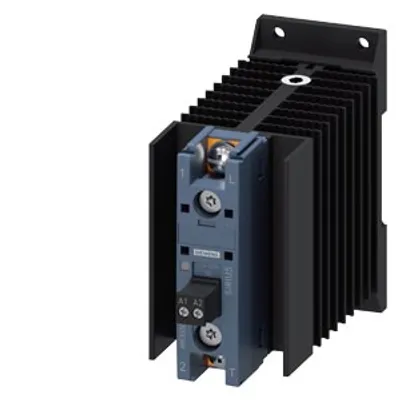
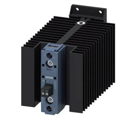
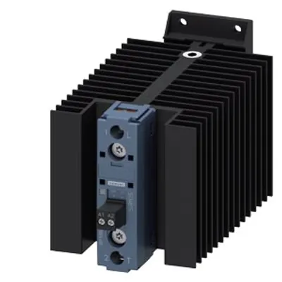
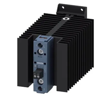
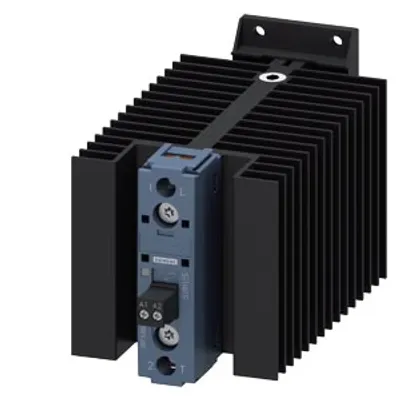
Siemens 3RF3365-3BA26
Solid-state contactor 1-pole 3RF3 AC-15 / 27.5 A / 40 °C 48-600 V 110-230 V AC instantaneous switching ring…
- MPN
- 3RF3365-3BA26
Price and lead time confirmed within 1 business day
Request a Quote
- 12-month warranty (new) · 3-month (used/refurbished)
- 30-day returns, no restocking fee on unused parts
- Ships via



- 100% positive eBay feedback
What is the Siemens 3RF3365-3BA26?
solid-state contactor 1-pole 3RF3 AC-15 / 27.5 A / 40 °C 48-600 V 110-230 V AC instantaneous switching ring cable terminal
Specifications
General technical data
| product function | instantaneous switching |
| product feature | high blocking voltage |
| power loss [V∙A] maximum | 65 V·A |
| power loss [W] for rated value of the current – at AC in hot operating state | 63 W |
| power loss [W] for rated value of the current – at AC in hot operating state per pole | 63 W |
| power loss [W] for rated value of the current – without load current share typical | 3.5 W |
| type of calculation of power loss current-dependent | linear |
| insulation voltage rated value | 600 V |
| degree of pollution | 3 |
| surge voltage resistance of main circuit rated value | 6 kV |
| protection class IP | IP00 |
| protection class IP on the front according to IEC 60529 | IP00 |
| shock resistance according to IEC 60068-2-27 | 15 g / 11 ms |
| vibration resistance according to IEC 60068-2-6 | 2 g |
| reference code according to IEC 81346-2 | Q |
| Substance Prohibitance (day/month/year) | 01/15/2024 |
| SVHC substance name | Lead CAS-No. 7439-92-1 Lead monoxide (lead oxide) CAS-No. 1317-36-8 2-methyl-1-(4-methylthiophenyl)-2-morpholinopropan-1-one CAS-No. 71868-10-5 Melamine CAS-No. 108-78-1 |
| Net Weight | 0.42 kg |
Main circuit
| number of poles for main current circuit | 1 |
| number of NO contacts for main contacts | 1 |
| number of NC contacts for main contacts | 0 |
| type of voltage of the operating voltage | AC |
| at AC – — at 50 Hz rated value | 48 ... 600 V |
| at AC – — at 60 Hz rated value | 48 ... 600 V |
| operating frequency rated value | 50 ... 60 Hz |
| relative symmetrical tolerance of the operating frequency | 10 % |
| operating range relative to the operating voltage at AC – at 50 Hz | 40 ... 660 V |
| operating range relative to the operating voltage at AC – at 60 Hz | 40 ... 660 V |
| operational current rated value maximum | 65 A |
| operational current – at AC-1 at 400 V rated value | 65 A |
| operational current – at AC-15 rated value | 27.5 A |
| operational current – at AC-51 rated value | 65 A |
| operational current – at AC-51 according to IEC 60947-4-3 | 65 A |
| operational current – according to UL 508 rated value | 56 A |
| ampacity maximum | 65 A |
| operational current minimum | 500 mA |
| rate of voltage rise at the thyristor for main contacts maximum permissible | 1 000 V/µs |
| blocking voltage at the thyristor for main contacts maximum permissible | 1 600 V |
| reverse current of the thyristor | 10 mA |
| derating temperature | 40 °C |
| surge current resistance rated value | 1 300 A |
| I2t value maximum | 8 000 A²·s |
Control circuit/ Control
| type of voltage of the control supply voltage | AC |
| control supply voltage at AC – at 50 Hz | 110 ... 230 V |
| control supply voltage at AC – at 60 Hz | 110 ... 230 V |
| control supply voltage 1 at AC – at 50 Hz | 110 ... 230 V |
| control supply voltage 1 at AC – at 60 Hz | 110 ... 230 V |
| control supply voltage at AC – at 50 Hz full-scale value for signal<0> recognition | 40 V |
| control supply voltage at AC – at 60 Hz full-scale value for signal<0> recognition | 40 V |
| control supply voltage at AC – initial value for signal <1> detection | 90 V |
| control supply voltage frequency – 1 rated value | 50 Hz |
| control supply voltage frequency – 2 rated value | 60 Hz |
| symmetrical line frequency tolerance | 5 Hz |
| operating range factor control supply voltage rated value at AC at 50 Hz – initial value | 0.82 |
| operating range factor control supply voltage rated value at AC at 60 Hz – initial value | 0.82 |
| control current at minimum control supply voltage – at AC | 2 mA |
| control current at AC rated value | 15 mA |
| ON-delay time | 40 ms |
| OFF-delay time | 40 ms; additionally max. one half-wave |
Installation/ mounting/ dimensions
| fastening method side-by-side mounting | Yes |
| fastening method | screw fixing and snap-on mounting on standard mounting rail 35 mm according to IEC 60715 |
| design of the thread of the screw for securing the equipment | M4 |
| height | 100 mm |
| width | 70 mm |
| depth | 144 mm |
Connections/ Terminals
| product component removable terminal for auxiliary and control circuit | Yes |
| type of electrical connection – for main current circuit | Ring cable lug connection |
| type of electrical connection – for auxiliary and control circuit | screw-type terminals |
| type of connectable conductor cross-sections – for main contacts for JIS cable lug | JIS C 2805 R 2-5, 5,5-5, 8-5, 14-5 |
| type of connectable conductor cross-sections – for AWG cables for main contacts | 1x (12 ... 4) |
| type of connectable conductor cross-sections – for DIN cable lug for main contacts | DIN 46234-5-2,5, -5-6, -5-10, -5-16, -5-25 |
| for auxiliary and control contacts – — solid | 1x (0.5 ... 2.5 mm²), 2x (0.5 ... 1 mm²) |
| for auxiliary and control contacts – — finely stranded with core end processing | 1x (0.5 ... 2.5 mm²), 2x (0.5 ... 1 mm²) |
| for auxiliary and control contacts – — finely stranded without core end processing | 1x (0.5 ... 2.5 mm²), 2x (0.5 ... 1 mm²) |
| for auxiliary and control contacts – for AWG cables for auxiliary and control contacts | 1x (20 ... 12) |
| AWG number as coded connectable conductor cross section for main contacts | 12 ... 4 |
| tightening torque – for main contacts with screw-type terminals | 2 ... 2.5 N·m |
| tightening torque – for auxiliary and control contacts with screw-type terminals | 0.5 ... 0.6 N·m |
| tightening torque [lbf·in] – for auxiliary and control contacts with screw-type terminals | 4.5 ... 5.3 lbf·in |
| design of the thread of the connection screw – for main contacts | M5 |
| design of the thread of the connection screw – of the auxiliary and control contacts | M3 |
| stripped length of the cable – for main contacts | 10 mm |
| stripped length of the cable – for auxiliary and control contacts | 7 mm |
| type of grounding | grounding heat sink by means of screw-type terminal |
UL/CSA ratings
| operational current according to UL 508 rated value | 56 A |
| touch protection on the front according to IEC 60529 | finger-safe, for vertical contact from the front with cover |
Ambient conditions
| installation altitude at height above sea level maximum | 1 000 m |
| ambient temperature – during operation | -25 ... +60 °C |
| ambient temperature – during storage | -55 ... +80 °C |
Electromagnetic compatibility
| conducted interference – due to burst according to IEC 61000-4-4 | 2 kV / 5 kHz, behavior criterion 2 |
| conducted interference – due to conductor-earth surge according to IEC 61000-4-5 | 2 kV, behavior criterion 2 |
| conducted interference – due to conductor-conductor surge according to IEC 61000-4-5 | 1 kV, behavior criterion 2 |
| conducted interference – due to high-frequency radiation according to IEC 61000-4-6 | 140 dBuV in the frequency range 0.15 ... 80 MHz, behavior criterion 1 |
| field-based interference according to IEC 61000-4-3 | 80 MHz ... 1 GHz 10 V/m, behavior criterion 1 |
| electrostatic discharge according to IEC 61000-4-2 | 4 kV contact discharging / 8 kV air discharging, behavior criterion 2 |
| conducted HF interference emissions according to CISPR11 | Class A for industrial environment |
| field-bound HF interference emission according to CISPR11 | Class B for the domestic, business and commercial environments |
Short-circuit protection, design of the fuse link
| manufacturer's article number – of full range R fuse link for semiconductor protection at NH design usable | 3NE8718-1 |
| manufacturer's article number – of gS fuse for semiconductor protection at NH design usable | 3NE1818-0 |
| manufacturer's article number – of back-up R fuse link for semiconductor protection at NH design usable | 3NE8020-1 |
| manufacturer's article number – of back-up R fuse link for semiconductor protection at cylindrical design 22 x 58 mm usable | 3NC2280 |
| manufacturer's article number of the gG fuse – at NH design usable | 3NA6812; These fuses have a smaller rated current than the semiconductor relays |
| manufacturer's article number of the gG fuse – at NH design usable note | These fuses have a smaller rated current than the semiconductor relays |
Downloads & documentation
Official documents from Siemens, downloaded directly from the manufacturer.
Data sheets & manuals
3RF3365-3BA26: frequently asked questions
When can 3RF3365-3BA26 be shipped?
3RF3365-3BA26 is sourced on request — request a quote and we'll confirm the exact availability and shipping timeline for this specific unit.
Can I pick up 3RF3365-3BA26 in person?
Local pickup from our Groningen, Netherlands warehouse may be possible — contact us before ordering to check availability and arrange a collection time.
Is express delivery available?
Yes — mention it when you request a quote for 3RF3365-3BA26 and we'll include express shipping options in our reply.
My factory is down and I need this urgently — can you help?
For a critical breakdown, contact us directly at +31 (0)50-7110348 or sales@partnerplc.com — we can look into same-day courier or dedicated taxi/hotshot delivery for 3RF3365-3BA26, subject to availability and destination.
More Siemens parts
Siemens 3RF3365-3BA26Price and lead time confirmed within 1 business day
Request a Quote