| Control: Control method: Common | Soft-PWM control/High carrier frequency PWM control |
| Control: Control method: Induction motor | Selectable among V/F control, Advanced magnetic flux vector control, Real sensorless vector control, and Vector control *11 |
| Control: Output frequency range: Induction motor | 0.2 to 590 Hz (The upper-limit frequency is 400 Hz under Advanced magnetic flux vector control, Real sensorless vector control, and Vector control *10 .) |
| Control: Frequency setting and resolution: Analog input | 0.015 Hz/60 Hz at 0 to 10 V/12 bits (terminals 2 and 4) 0.03 Hz/60 Hz at 0 to 5 V/11 bits or 0 to 20 mA/11 bits (terminals 2 and 4), at 0 to ±10 V/12 bits (terminal 1) 0.06 Hz/60 Hz at 0 to ±5 V/11 bits (terminal 1) |
| Control: Frequency setting and resolution: Digital input | 0.01 Hz |
| Control: Frequency accuracy: Analog input | Within ±0.2 % of the maximum output frequency (25 °C ±10 °C) |
| Control: Frequency accuracy: Digital input | 0.01 % or less of the set output frequency |
| Control: Voltage/frequency characteristics | Base frequency can be set from 0 to 590 Hz. Constant-torque/variable-torque pattern or adjustable 5 points V/F can be selected. |
| Control: Starting torque: Induction motor | The following is the specifications for the ND rating. 30 % or less at 1 Hz, 30 % at 3 Hz, 80 % at 6 Hz (V/F control) 150 % at 0.5 Hz (Advanced magnetic flux vector control) 150 % at 0.3 Hz (Real sensorless vector control) 150 % at 0 Hz (Vector control *11 ) |
| Control: Torque boost | Manual torque boost (induction motor only) |
| Control: Acceleration/deceleration time setting | 0 to 3600 s (acceleration and deceleration can be set individually), linear or S-pattern acceleration/deceleration mode, backlash countermeasures acceleration/deceleration modes are available. |
| Control: DC injection brake: Induction motor | Operation frequency (0 to 120 Hz), operation time (0 to 10 s), operation voltage (0 to 30 %) variable |
| Control: Stall prevention operation level | Activation range of stall prevention operation (ND rating : 0 % to 220 %). Whether to use the stall prevention or not can be selected. (V/F control, Advanced magnetic flux vector control) |
| Control: Torque limit level | Torque limit value can be set (0 to 400 % variable). (Real sensorless vector control, Vector control *7 ) |
| Operation: Frequency setting signal: Number of analog input | 3 |
| Operation: Frequency setting signal: Specification of analog input | Terminals 2 and 4 : 0 to 10 V/0 to 5 V/4 to 20 mA (0 to 20 mA) Terminal 1 : -10 to +10 V/-5 to +5 V |
| Operation: Frequency setting signal: Digital input | Input using the setting dial of the operation panel or parameter unit. Input of four-digit BCD (Binary-coded decimal) or 16-bit binary (when the option FR-A8AX is installed). |
| Operation: Start signal | Forward and reverse rotation or start signal automatic self-holding input (3-wire input) can be selected. |
| Operation: Input signal: Number of input signal (Contact input) | 12 |
| Operation: Input signal: Pulse train input | 100 k pulses/s |
| Operation: Input signal: Input terminal function selectable signal | Low-speed operation command, Middle-speed operation command, High-speed operation command, Second function selection, Terminal 4 input selection, Jog operation selection, Selection of automatic restart after instantaneous power failure/flying start, Output stop, Start self-holding selection, Forward rotation command, Reverse rotation command, Inverter reset The signal to be input can be changed us |
| Operation: Operational function | Maximum and minimum frequency settings, Multi-speed operation, Acceleration/deceleration pattern, Thermal protection, DC injection brake, Starting frequency, JOG operation, Output stop (MRS), Stall prevention, Regeneration avoidance, Increased magnetic excitation deceleration, Frequency jump, Rotation display, Automatic restart after instantaneous power failure, Electronic bypass sequence, Remote |
| Operation: Output signal: Number of output signal (Open collector output) | 5 |
| Operation: Output signal: Number of output signal (Relay output) | 2 |
| Operation: Output signal: Output terminal function selectable signal | Inverter running, Up to frequency, Instantaneous power failure/undervoltage, Overload warning, Output frequency detection, Fault The signal to be output can be changed using Pr.190 to Pr.196 (Output terminal function selection). Fault codes (4 bits) of the inverter can be output from the open collector. |
| Operation: Output signal: Pulse train output (FM type inverter) | 50 k pulses/s |
| Indication: For indication on external meters: Number of output signal for indication on external meters | 2 |
| Indication: For indication on external meters: Pulse train output (FM type inverter) | Max. 2.4 kHz via one terminal (for the indication of inverter output frequency). The item for monitoring can be changed using Pr.54 FM/CA terminal function selection. |
| Indication: For indication on external meters: Current output (CA type inverter) | Max. 20 mA DC via one terminal (for the indication of inverter output frequency). The item for monitoring can be changed using Pr.54 FM/CA terminal function selection. |
| Indication: For indication on external meters: Voltage output | Max. 10 V DC via one terminal (for the indication of inverter output frequency). The item for monitoring can be changed using Pr.158 AM terminal function selection. |
| Indication: Operation panel: Status monitoring | Output frequency, output current, output voltage, and frequency setting value are monitored. The item for monitoring can be changed using Pr.52 Operation panel main monitor selection. |
| Indication: Operation panel: Fault monitoring | When a protective function is activated, a fault indication is displayed and the output voltage, output current, output frequency, cumulative energization time, date (year, month, day) and time at the occurrence of the fault are stored. Each fault is recorded and the last 8 records can be displayed. |
| Protective/warning function: Protective function | Overcurrent trip during acceleration, Overcurrent trip during constant speed, Overcurrent trip during deceleration or stop, Overcurrent trip, Regenerative overvoltage trip during acceleration, Regenerative overvoltage trip during constant speed, Regenerative overvoltage trip during deceleration or stop, Overvoltage trip, Inverter overload trip (electronic thermal relay function), Motor overload tr |
| Protective/warning function: Warning function | Fan alarm, Stall prevention (overcurrent), Stall prevention (overvoltage), Electronic thermal relay function pre-alarm, PU stop, Speed limit indication *15 , Continuous operation during communication fault, Parameter copy, Safety stop, Maintenance timer *15 , USB host error, Home position return setting error *15 , Home position return uncompleted *15 , Operation panel lock *15 , Password locked * |
| Environment: Noise *16 | 74 dB (single-unit operation) |
| Environment: Surrounding air temperature | -10 °C to +40 °C (non-freezing) |
| Environment: Surrounding air humidity | 95 % RH or less (non-condensing) |
| Environment: Storage temperature *13 | -20 °C to +65 °C |
| Environment: Ambience | Indoors (free from corrosive gas, flammable gas, oil mist, dust and dirt) |
| Environment: Altitude/vibration | Maximum 4000 m *14 .Frequency range 10 to 57 Hz : maximum amplitude 0.075 mm. Frequency range 57 to 150 Hz : maximum acceleration speed 1 G. |
| Network | Option unit : CC-Link IE TSN, CC-Link IE Field Network, CC-Link, SSCNETIII(/H), DeviceNet, PROFIBUS-DPV0, FL remote, EtherCAT, EtherNet/IP, PROFINET, PROFIBUS-DPV1 |





.svg&w=240)





















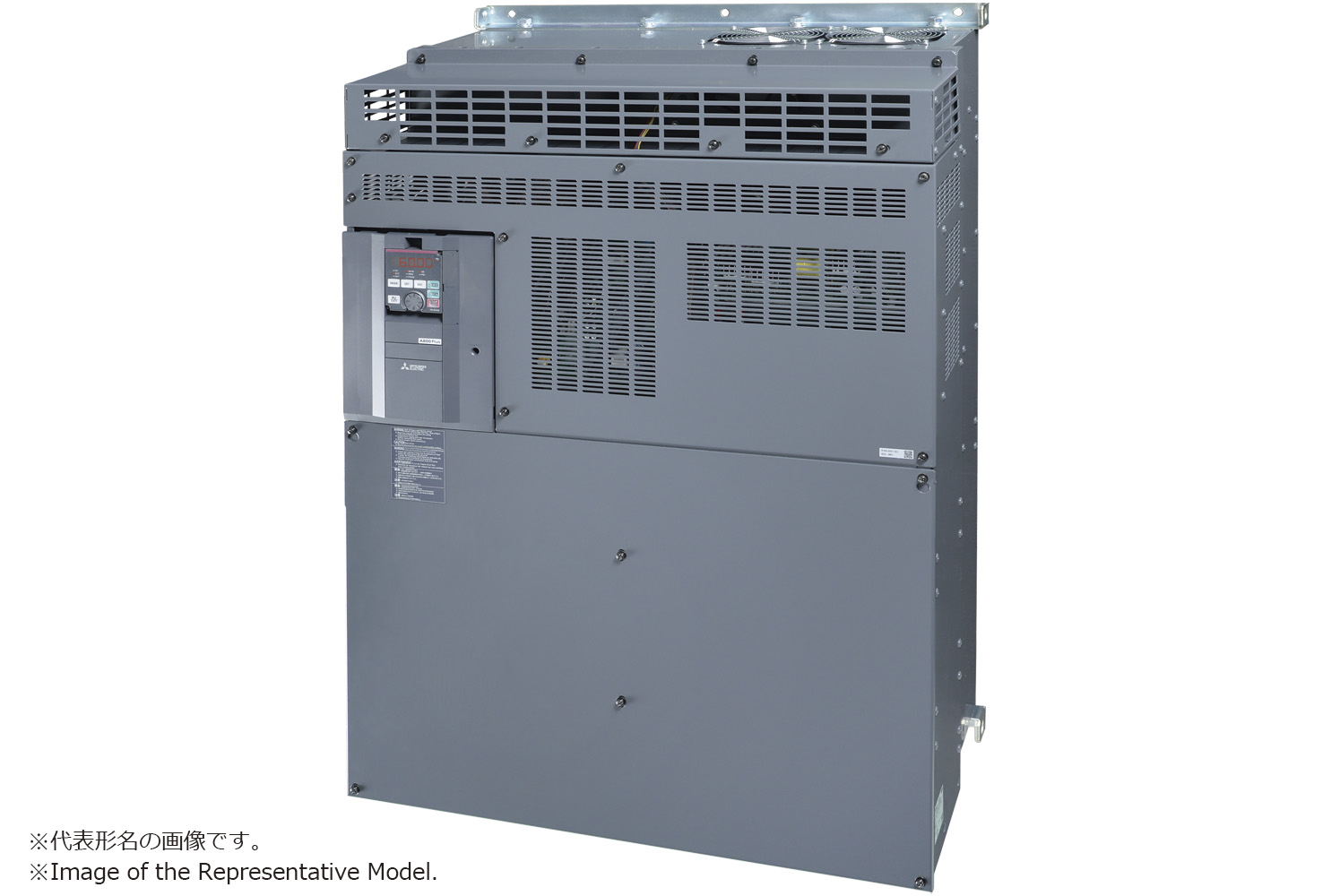 Available on requestFR-A870-04560-1-60LC Mitsubishi FREQROL inverter FR-A800 Plus
 Available on requestFR-A872-05690-E1-60 Mitsubishi FREQROL inverter FR-A800