




.svg&w=240)


















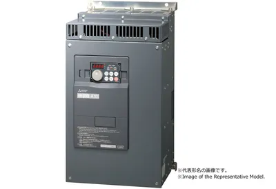
FR-A721-7.5K Mitsubishi FREQROL inverter FR-A701
Request a Quote



Quick facts
| Availability | Confirmed on request |
| Category | Mitsubishi FREQROL inverter – FREQROL-A701 |
| Lifecycle | Active |
| Warranty | 12-month (new) · 3-month (used/refurbished) |
Shipping & availability
When can FR-A721-7.5K be shipped?
FR-A721-7.5K is sourced on request — request a quote and we'll confirm the exact availability and shipping timeline for this specific unit.
Can I pick up FR-A721-7.5K in person?
Local pickup from our Groningen, Netherlands warehouse may be possible — contact us before ordering to check availability and arrange a collection time.
Is express delivery available?
Yes — mention it when you request a quote for FR-A721-7.5K and we'll include express shipping options in our reply.
My factory is down and I need this urgently — can you help?
For a critical breakdown, contact us directly at +31 (0)50-7110348 or sales@partnerplc.com — we can look into same-day courier or dedicated taxi/hotshot delivery for FR-A721-7.5K, subject to availability and destination.
The Mitsubishi Electric FR-A721-7.5K is a FR-A701 in the FREQROL inverter. cULus. Specifications and manuals below are Mitsubishi Electric's own data.
Specifications
Product
| Series | FREQROL inverter |
| Category | FR-A701 |
| Outline | cULus |
Specifications
| Series | FR-A701 |
| Type | Three-phase 200 V class |
| Model name | FR-A721-7.5K |
| Inverter capacity (kW) | 7.5 |
| Applicable motor capacity (kW) *1 | 7.5 |
| Output: Rated capacity (kVA) *2 | 12.6 |
| Output: Rated current (A) | 33.0 |
| Output: Overload current rating *3 | 150 % 60 s, 200 % 3 s (inverse-time characteristics) surrounding air temperature 50 °C |
| Output: Voltage *4 | Three-phase 200 to 240 V |
| Output: Regenerative braking: Maximum brake torque (ND reference) | 100 % continuous 150 % 60 s |
| Power supply: Rated input AC voltage and frequency | Three-phase 200 to 220 V 50 Hz, 200 to 240 V 60 Hz |
| Power supply: Permissible AC voltage fluctuation | 170 to 242 V 50 Hz,170 to 264 V 60 Hz |
| Power supply: Permissible frequency fluctuation | ±5 % |
| Power supply: Power supply capacity (kVA) without DC reactor *5 | 17.0 |
| Protective structure: JEM 1030 *6 | IP00 |
| Cooling system | Forced air cooling |
| Approx. mass (kg) | 22.0 |
| Control: Control method: Common | Soft-PWM control/high carrier frequency PWM control |
| Control: Control method: Induction motor | Selectable among V/F control, Advanced magnetic flux vector control, Real sensorless vector control, and Vector control *7 |
| Control: Control method: PM motor | PM sensorless vector control |
| Control: Output frequency range: Induction motor | 0.2 to 400 Hz (The maximum frequency is 120 Hz under Real sensorless vector control and vector control *7 .) |
| Control: Frequency setting and resolution: Analog input | 0.015 Hz/60 Hz (terminal 2, 4 : 0 to 10 V/12 bit) 0.03 Hz/60 Hz (terminal 2, 4 : 0 to 5 V/11 bit, 0 to 20 mA/about 11 bit, terminal 1 : 0 to ±10 V/12 bit) 0.06 Hz/60 Hz (terminal 1 : 0 to ±5 V/11 bit) |
| Control: Frequency setting and resolution: Digital input | 0.01 Hz |
| Control: Frequency accuracy: Analog input | Within ±0.2 % of the max. output frequency (25 °C ±10 °C) |
| Control: Frequency accuracy: Digital input | Within 0.01 % of the set output frequency |
| Control: Voltage/frequency characteristics | Base frequency can be set from 0 to 400 Hz Constant torque/variable torque pattern or adjustable 5 points V/F can be selected |
| Control: Starting torque: Induction motor | The following is the specifications for the ND rating. 30 % or less at 1 Hz, 30 % at 3 Hz, 80 % at 6 Hz (V/F control) 150 % at 0.5 Hz (Advanced magnetic flux vector control) 150 % at 0.3 Hz (Real sensorless vector control) 150 % at 0 Hz (Vector control *7 ) |
| Control: Starting torque: PM motor | The following is the specifications for the ND rating. 50 % (current synchronization operation) 150 % (with MM-CF) (high frequency superposition control) |
| Control: Torque boost | Manual torque boost |
| Control: Acceleration/deceleration time setting | 0 to 3600 s (acceleration and deceleration can be set individually), linear or S-pattern acceleration/deceleration mode, backlash measures acceleration/deceleration mode are available. |
| Control: DC injection brake: Induction motor | Operation frequency (0 to 120 Hz), operation time (0 to 10 s), operation voltage (0 to 30 %) variable |
| Control: DC injection brake: PM motor | Operation time (0 to 10 s) variable. Operating voltage (operating current) fixed. |
| Control: Stall prevention operation level | Operation current : 0 to 220 % variable, with selectable availability of the function |
| Control: Torque limit level | Torque limit value can be set (0 to 400 % variable) |
| Operation: Frequency setting signal: Number of analog input | 3 |
| Operation: Frequency setting signal: Specification of analog input | Terminals 2 and 4 : 0 to 10 V/0 to 5 V/4 to 20 mA (0 to 20 mA) Terminal 1 : -10 to +10 V/-5 to +5 V |
| Operation: Frequency setting signal: Digital input | Input using the setting dial of the operation panel or parameter unit. Input of four-digit BCD (Binary-coded decimal) or 16-bit binary (when the option FR-A7AX is installed). |
| Operation: Start signal | Forward and reverse rotation or start signal automatic self-holding input (3-wire input) can be selected. |
| Operation: Input signal: Number of input signal (Contact input) | 12 |
| Operation: Input signal: Pulse train input | 100 k pulses/s |
| Operation: Input signal: Input terminal function selectable signal | Multi speed selection, Remote setting, Stopon-contact, Second function selection, Third function selection, Terminal 4 input selection, JOG operation selection, Selection of automatic restart after instantaneous power failure/flying start, External thermal relay input, PU operation/external inter lock signal, External DC injection brake operation start, PID control enable terminal, Brake opening c |
| Operation: Operational function | Maximum and minimum frequency settings, Frequency jump, External thermal relay input selection, Polarity reversible operation, Automatic restart after instantaneous power failure, Electronic bypass sequence, Forward/reverse rotation prevention, Remote setting, Brake sequence, Second function, Third function, Multi-speed operation, Original operation continuation at instantaneous power failure, Sto |
| Operation: Output signal: Number of output signal (Open collector output) | 5 |
| Operation: Output signal: Number of output signal (Relay output) | 2 |
| Operation: Output signal: Output terminal function selectable signal | Inverter running1, Inverter running2, Inverter running/start command on, Up-to-frequency, Instantaneous power failure/undervoltage, Overload warning, Output frequency (speed) detection, Second output frequency (speed) detection, Third output frequency (speed) detection, Electronic thermal relay function pre-alarm, PU operation mode, Inverter operation ready1, Inverter operation ready2, Output curr |
| Operation: Output signal: Output terminal function selectable signal (When used with the option) | In addition to above, the following signal can be assigned to Pr. 313 to Pr. 319 (extension output terminal function selection): control circuit capacitor life, main circuit capacitor life, cooling fan life, inrush current limit circuit life. (only positive logic can be set for extension terminals of the FR-A7AR) |
| Operation: Output signal: Pulse train output (FM type inverter) | 50 k pulses/s |
| Indication: For indication on external meters: Number of output signal for indication on external meters | 2 |
| Indication: For indication on external meters: Pulse train output (FM type inverter) | Max. 2.4 kHz via one terminal (for the indication of inverter output frequency). The item for monitoring can be changed using Pr.54 FM terminal function selection : output frequency, motor current (steady or peak value), output voltage, frequency setting, operation speed, motor torque, converter output voltage (steady or peak value), electronic thermal relay function load factor, input power, outp |
| Indication: For indication on external meters: Voltage output | Max. 10 V DC via one terminal (for the indication of inverter output frequency). The item for monitoring can be changed using Pr.158 AM terminal function selection : output frequency, motor current (steady or peak value), output voltage, frequency setting, operation speed, motor torque, converter output voltage (steady or peak value), electronic thermal relay function load factor, input power, out |
| Indication: Operation panel Parameter unit (FR-PU07): Status monitoring | The following operating status can be displayed : Output frequency, motor current (steady or peak value), output voltage, frequency setting, running speed, motor torque, overload, converter output voltage (steady or peak value), electronic thermal relay function load factor, input power, output power, load meter, motor excitation current, position pulse *7 , cumulative energization time, orientati |
| Indication: Operation panel Parameter unit (FR-PU07): Fault monitoring | Fault record is displayed when a fault occurs, the output voltage/current/frequency/cumulative energization time right before the fault occurs and past 8 fault records are stored. |
| Indication: Operation panel Parameter unit (FR-PU07): Interactive guidance | Function (help) for operation guide *10 |
| Protective/warning function: Protective function | Overcurrent trip during acceleration, Overcurrent trip during constant speed, Overcurrent trip during deceleration or stop, Regenerative overvoltage trip during acceleration, Regenerative overvoltage trip during constant speed, Regenerative overvoltage trip during deceleration or stop, Inverter overload trip (electronic thermal relay function), Motor overload trip (electronic thermal relay functio |
| Protective/warning function: Warning function | Fan alarm, Stall prevention (overcurrent), Stall prevention (overvoltage), Electronic thermal relay function pre-alarm, PU stop, Maintenance timer *9 *12 , Parameter write error, Copy operation error, Operation panel lock, Password locked, Parameter copy, Speed limit indication |
| Environment: Surrounding air temperature | -10 °C to +50 °C (non-freezing) |
| Environment: Surrounding air humidity | 90 % RH or less (non-condensing) |
| Environment: Storage temperature *11 | -20 °C to +65 °C |
| Environment: Ambience | Indoors (free from corrosive gas, flammable gas, oil mist, dust and dirt) |
| Environment: Altitude/vibration | Maximum 1000 m, 5.9 m/s 2 or less at 10 to 55 Hz in X, Y, and Z directions |
| Network | RS-485 : Mitsubishi inverter protocol, MODBUS RTU Option unit : CC-Link IE Field Network, CC-Link, SSCNETIII, DeviceNet, PROFIBUS-DPV0, LONWORKS, FL remote |
Downloads & documentation
Official documents from Mitsubishi Electric (Factory Automation), downloaded directly from the manufacturer.
Data sheets & manuals
| FR-A701 INSTRUCTION MANUAL (BASIC) (IB-0600331ENG-F) | PDF · 8.87MB |
| FR-A701 INSTRUCTION MANUAL (Applied) (IB-0600337ENG-D) | PDF · 11.81MB |
More Mitsubishi Electric (Factory Automation) parts
 Available on requestFR-A721-37K Mitsubishi FREQROL inverter FR-A701Available on requestFR-A721-45K Mitsubishi FREQROL inverter FR-A701Available on requestFR-A721-5.5K Mitsubishi FREQROL inverter FR-A701Available on requestFR-A721-55K Mitsubishi FREQROL inverter FR-A701Available on requestFR-A741-11K Mitsubishi FREQROL inverter FR-A701Available on requestFR-A741-15K Mitsubishi FREQROL inverter FR-A701Available on requestFR-A741-18.5K Mitsubishi FREQROL inverter FR-A701Available on requestFR-A741-22K Mitsubishi FREQROL inverter FR-A701