
























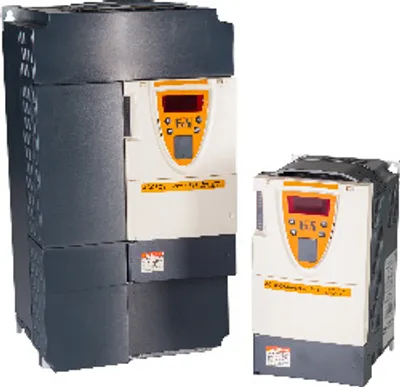
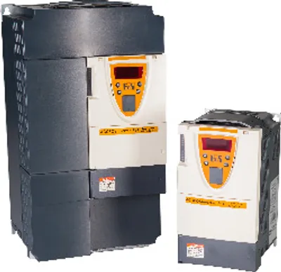
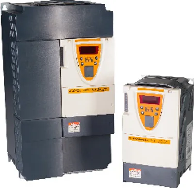
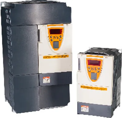
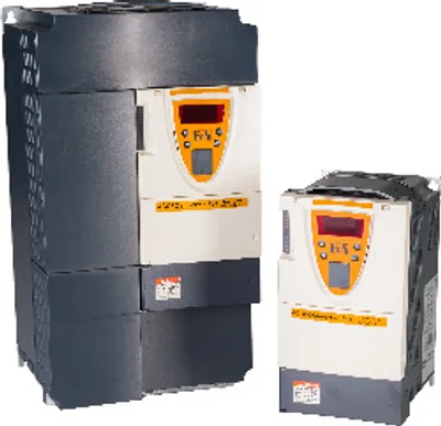
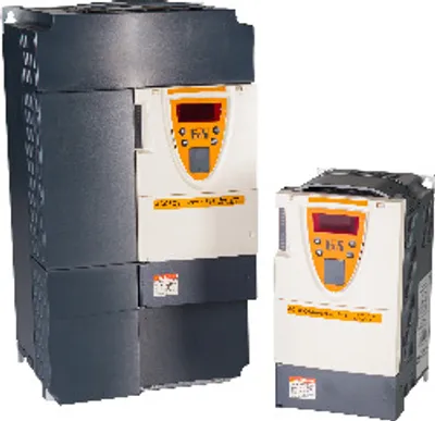
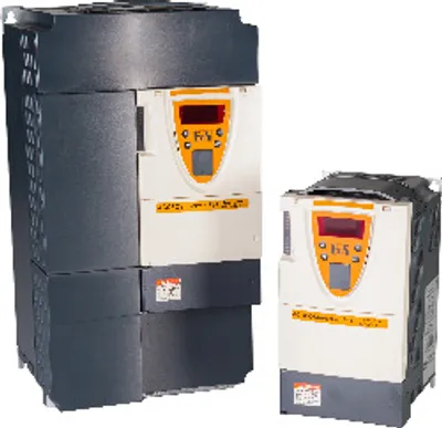
B&R 8I84T200300.01P-1
ACOPOSinverter P84, 3x 200 to 240 V, 3 kW and 1x 200 to 240 V, 2.2 kW
- MPN
- 8I84T200300.01P-1
Price and lead time confirmed within 1 business day
Request a Quote
- 1We check stock, condition and lead time
- 2You get a written quote by email
- 3Approve it and we ship — in-stock parts within 1 business day
- 12-month warranty (new) · 3-month (used/refurbished)
- 30-day returns, no restocking fee on unused parts
- 100% positive eBay feedback
- Ships via



What is the B&R 8I84T200300.01P-1?
ACOPOSinverter P84, 3x 200 to 240 V, 3 kW and 1x 200 to 240 V, 2.2 kW, integrated EMC filter and brake chopper, shield plate included in delivery, POWERLINK interface.
Specifications
General information
| Certifications – CE | Yes |
| Certifications – UL | cULus E225616; Power conversion equipment |
| Certifications – KC | Yes |
Motor power
| Specified on nameplate, 1-phase | 2.2 kW ; 3 PS |
| Specified on nameplate, 3-phase | 3 kW ; - |
Mains connection
| Max. mains current with optional mains choke – At 230 VAC | 11.0 A |
| Mains current – At 200 VAC, 1-phase | 25.9 A (note: Typical value for the specified motor power and the max. assumed short-circuit current (lsc).) |
| Mains current – At 200 VAC, 3-phase | 19.3 A (note: Typical value for the specified motor power and the max. assumed short-circuit current (lsc).) |
| Mains current – At 240 VAC, 1-phase | 22.1 A (note: Typical value for the specified motor power and the max. assumed short-circuit current (lsc).) |
| Mains current – At 240 VAC, 3-phase | 16.4 A (note: Typical value for the specified motor power and the max. assumed short-circuit current (lsc).) |
| Mains input voltage, 1-phase | 1x 200 VAC -15% to 240 VAC +10% |
| Mains input voltage, 3-phase | 3x 200 VAC -15% to 240 VAC +10% |
| Frequency | 50 to 60 Hz ±5% |
| Apparent power (at 240 VAC), 1-phase | 5.3 kVA |
| Apparent power (at 240 VAC), 3-phase | 6.8 kVA |
| Max. assumed short-circuit current (Isc); (short-circuit current at connection point) | 5 kA |
| Power dissipation at nominal load and nominal clock frequency | 154 W |
| Integrated EMC filter | Yes (note: Shield plate included in delivery) |
Line-conducted and radiated emissions
| With integrated filter – Motor cable length per IEC/EN 61800-3 ; Cat. C1 environment 1 (public power network) | - |
| With integrated filter – Motor cable length per IEC/EN 61800-3 ; Cat. C2 environment 1 (public power network) | - |
| With integrated filter – Motor cable length per IEC/EN 61800-3 ; Cat. C3 environment 2 (industrial power system) | ≤10 m / ≤5 m (note: For shielded motor cables ≤10 m → At a clock frequency of 4 kHz ≤5 m → At a clock frequency of 4.1 to 16 kHz) |
| With add-on filter – Motor cable length per IEC/EN 61800-3 ; Cat. C1 environment 1 (public power network) | ≤50 m / ≤20 m (note: For shielded motor cables ≤50 m → At a clock frequency of 4 kHz ≤20 m → At a clock frequency of 4.1 to 16 kHz) |
| With add-on filter – Motor cable length per IEC/EN 61800-3 ; Cat. C2 environment 1 (public power network) | ≤100 m / ≤50 m (note: For shielded motor cables ≤100 m → At a clock frequency of 4 kHz ≤50 m → At a clock frequency of 4.1 to 16 kHz) |
| With add-on filter – Motor cable length per IEC/EN 61800-3 ; Cat. C3 environment 2 (industrial power system) | ≤100 m / ≤50 m (note: For shielded motor cables ≤100 m → At a clock frequency of 4 kHz ≤50 m → At a clock frequency of 4.1 to 16 kHz) |
| With add-on filter | 8I0FT026.300-1 |
Motor connection
| Derating of continuous output current depending on ambient temperature – At nominal clock frequency (4 kHz or 2.5 kHz with higher inverter power) | No derating (up to 50°C) |
| Derating of continuous output current depending on ambient temperature – Other clock frequencies | The derating curves are included in the installation instructions, which can be downloaded from the website (www.br-automation.com). |
| Derating of continuous output current depending on installation elevation – Starting at 1000 m above sea level | 1%, per 100 m |
| Max. continuous output current (In) – At 230 VAC, 1-phase | 11 A (note: These values are valid for the rated clock frequency.) |
| Max. continuous output current (In) – At 230 VAC, 3-phase | 13.7 A (note: These values are valid for the rated clock frequency.) |
| Nominal clock frequency – Min. | 1 kHz |
| Nominal clock frequency – Max. | 16 kHz |
| Braking torque – With braking resistor | Up to 150% of the rated motor torque |
| Braking torque – Without braking resistor (typical value) | 30% of the rated motor torque |
| Max. motor cable length – Shielded cable | 50 m (note: These values are valid for the rated clock frequency.) |
| Max. motor cable length – Non-shielded cable | 100 m (note: These values are valid for the rated clock frequency.) |
| Motor control profiles – Induction motor | Flux vector control (FVC) with encoder (voltage vector) (current vector) ; Flux vector control (SFVC) without encoder (voltage or current vector) ; Voltage/frequency ratio - V/f characteristic curve (2 or 5 points) ; ENA energy adjustment system for asymmetrical loads |
| Max. transient current for 60 s, 1-phase | 16.5 A |
| Max. transient current for 60 s, 3-phase | 20.6 A |
| Max. transient current for 2 s, 1-phase | 18.1 A |
| Max. transient current for 2 s, 3-phase | 22.6 A |
| Output frequency range | 0.5 to 599 Hz |
| Nominal clock frequency | 4 kHz |
| Short-term overload torque (typical value) | 170% of the motor's rated torque (typical value at ±10%) for 60 s ; 220% of the motor's rated torque (typical value at ±10%) for 2 s |
| Main protective functions of inverter | Thermal protection against power stage overheating; Protection against short circuits between the motor phases, line phase failures, overcurrent between output phases and ground, overvoltages on the DC bus, interruptions in the control loop, exceeding the speed limit. Safety function for: Over- and undervoltage of the power supply system, line phase failure with 3-phase supply |
| Motor protection | Thermal protection integrated in the inverter through continually calculating the l²t value while taking the speed into consideration: ; -The thermal state of the motor is stored when the frequency inverter is switched off. ; -The functionality can be adjusted according to the motor type (external cooling or self-cooling) using an operator interface. ; Protection against motor phase failures ; Protection provided by PTC sensors |
Brake chopper
| Integrated dynamic brake transistors | Yes |
| Operating ratio for dynamic brake transistors | The dynamic brake transistor is designed to tolerate the following values: ; -Nominal motor power continuously ; -150% of the nominal motor power for 60 s |
| Min. resistance value (external) | 22 Ω (note: The min. resistance value is specified at a temperature of 20°C.) |
24 VDC power supply
| Input voltage | 24 VDC (min. 19 V, max. 30 V) |
| Power consumption | 30 W |
Available internal power supplies
| Output voltage 24 VDC – Max. output current at 24 VDC | 200 mA |
| Output voltage 10.5 VDC – Max. output current 10.5 VDC | 10 mA |
| Output voltage 24 VDC | 24 VDC (min. 21 V, max. 27 V) |
| Output voltage 10.5 VDC | 10.5 VDC ±5% |
Safe input - Power removal
| Switching threshold – Low | <5 V |
| Switching threshold – High | >15 V |
| Electrical isolation – Input - ACOPOSinverter | Yes |
| Electrical isolation – Input - Input | No |
| Quantity | 1 |
| Nominal voltage | 24 VDC |
| Response time | ≤100 ms |
| Input impedance | 1.5 kΩ |
| Input circuit | Sink |
Interfaces
| POWERLINK – Type | Type 3Communication / POWERLINK / General information / Hardware - IF/LS" for more information."> (note: See Automation Help under) |
Digital inputs
| Electrical isolation – Input - ACOPOSinverter | Yes |
| Electrical isolation – Input - Input | No |
| Quantity | 6 (note: 1 logic input, configurable as a logic input or PTC sensor input using a switch. Input for max. 6 PTC sensors in series: Nominal value <1.5 kΩ, 3 kΩ trigger resistance, 1.8 kΩ reset value, short-circuit proof <50 Ω) |
| Nominal voltage | 24 VDC |
| Input circuit | Source or sink |
| Sampling time | <2 ms ±0.5 ms |
| Input impedance | 3.5 kΩ |
Analog inputs
| Electrical isolation – Input - Input | No |
| Electrical isolation – Input - ACOPOSinverter | Yes |
| Input – Voltage | ±10 V |
| Input – Voltage/Current | 0 to 10 V or 0 to 20 mA |
| Input impedance – Voltage | 30 kΩ |
| Input impedance – Current | 242 Ω |
| Quantity | 2 |
| Resolution | ±11 bits |
| Sampling time | <2 ms ±0.5 ms |
Relay outputs
| Switching capacity – With resistive load (cos φ = 1 and L/R = 0 ms) | 2 A for 250 VAC or 30 VDC |
| Switching capacity – With inductive load (cos φ = 0.4 and L/R = 7 ms) | 1.5 A for 250 VAC or 30 VDC |
| Switching capacity – Min. | 3 mA for 24 VDC |
| Variant – Relay 1 | 1 NO contact and 1 NC contact with a common point |
| Variant – Relay 2 | 1 NO contact |
| Electrical isolation – Output - ACOPOSinverter | Yes |
| Electrical isolation – Output - Output | No |
| Quantity | 2 |
| Nominal voltage | 30 VDC / 250 VAC |
| Switching capacity | Max. 2 A for 250 VAC or 30 VDC with resistive load |
| Response time (max.) | <7 ms ±0.5 ms |
Analog outputs
| Electrical isolation – Output - ACOPOSinverter | Yes |
| Electrical isolation – Output - Output | No |
| Max. load impedance – Voltage | 470 Ω |
| Max. load impedance – Current | 500 Ω |
| Quantity | 1 |
| Output | 0 to 10 V or 0 to 20 mA (note: The analog output is configurable as a logic output.) |
| Update time | <2 ms ±0.5 ms |
| Resolution | 10-bit |
Operating conditions
| Installation elevation above sea level | 0 to 1000 m |
| Degree of protection per EN 60529 | Upper part: IP21 and IP41 ; Lower part: IP54 (heat sink) |
| Ambient temperature | -10 to 50°C |
| Max. ambient temperature | Up to 60°C |
| Relative humidity per IEC 60068-2-3 | 5 to 95%, non-condensing ; No dripping water |
| Maximum installation elevation | Up to 3000 m (note: From 1000 to 3000 m, current reduced by 1% per 100 m) |
| Max. pollution degree per IEC/EN 61800-5-1 | 2 (non-conductive pollution) |
| Ambient conditions per IEC 60721-3-3 | Class 3C1 and 3S2 |
| Operating position | Vertical mounting orientation ±10% |
Ambient conditions
| Temperature – Storage | -25 to 70°C |
| Vibration – Operation | 3 to 13 Hz: 1.5 mm amplitude / 13 to 200 Hz: 1 g |
| Shock – Operation | 15 g, 11 ms |
Mechanical properties
| Dimensions – Width | 155 mm |
| Dimensions – Height | 260 mm |
| Dimensions – Depth | 187 mm |
| Weight | 4 kg |
No matching specifications
Accessories
Optional accessories (22)
| 8I0XD304.310-1 | Cable and adapters — RJ45 cable, 10 m, for remote use of the display for the ACOPOSinverter. |
| 8I0XD304.305-1 | Cable and adapters — RJ45 cable, 5 m, for remote use of the display for the ACOPOSinverter. |
| 8I0XD304.303-1 | Cable and adapters — RJ45 cable, 3 m, for remote use of the display for the ACOPOSinverter. |
| 8I0XD304.301-1 | Cable and adapters — RJ45 cable, 1 m, for remote use of the display for the ACOPOSinverter. |
| 8I0DC027.300-1 | DC bus choke — DC bus choke 27 A, for ACOPOSinverter P84 3x 200 to 240 V, 3 kW and 3x 380 to 480 V, 11 kW. |
| 8I0XF084.030-1 | Fans (spare part) — Fan for ACOPOSinverter P84 3x 200 to 240 V, 2.2 to 4 kW and 3x 380 to 480 V, 3 to 4 kW. |
| 8I0MF002.300-1 | Feed-through mounting kits — Feed-through mounting kit, for ACOPOSinverter P84 3x 200 to 240 V, 2.2 to 4 kW and 3x 380 to 480 V, 3 to 4 kW. |
| 8I0XD305.300-1 | Graphic display — Female to female adapter, RJ45, for graphics display of the ACOPOSinverter. |
| 8I0XD303.300-1 | Graphic display — Front cover for installation kit, IP65 protection, for graphic display of the ACOPOSinverter. |
| 8I0XD302.300-1 | Graphic display — Installation kit, IP54 protection, for graphic display of the ACOPOSinverter. |
| 8I0XD301.300-1 | Graphic display — Graphics display for ACOPOSinverter, 240 x 160 pixels, 8 lines, backlight, function keys, navigation key, IP54 protection. |
| 8I0AC123.306-1 | Incremental encoder interfaces — ACOPOSinverter P84 plug-in module, incremental encoder interface for push-pull HTL, 24 V supply voltage. |
| 8I0AC123.305-1 | Incremental encoder interfaces — ACOPOSinverter P84 plug-in module, incremental encoder interface for push-pull HTL, 15 V supply voltage. |
| 8I0AC123.304-1 | Incremental encoder interfaces — ACOPOSinverter P84 plug-in module, incremental encoder interface for push-pull HTL, 12 V supply voltage. |
| 8I0AC123.303-1 | Incremental encoder interfaces — ACOPOSinverter P84 plug-in module, incremental encoder interface for open collector, 15 V supply voltage. |
| 8I0AC123.302-1 | Incremental encoder interfaces — ACOPOSinverter P84 plug-in module, incremental encoder interface for open collector, 12 V supply voltage. |
| 8I0AC123.301-1 | Incremental encoder interfaces — ACOPOSinverter P84 plug-in module, incremental encoder interface for RS422 signals (TTL), 15 V supply voltage. |
| 8I0AC123.300-1 | Incremental encoder interfaces — ACOPOSinverter P84 plug-in module, incremental encoder interface for RS422 signals (TTL), 5 V supply voltage. |
| 8I0FT026.300-1 | Optional EMC filters — 26 A EMC filter for ACOPOSinverter P84 (3-phase 200-240 V, 2.2-4 kW and 380-480 V, 3-4 kW). |
| 8I0BR028.000-1 | Optional braking resistors — Braking resistor ohmic value: 28 Ω continuous braking power: 0.20 kW degree of protection (IP): IP20 |
| 8I0CT016.000-1 | Optional line chokes — Mains choke 3-phase, 17 A, 50/60 Hz for ACOPOSinverter |
| 8I0CS025.000-1 | Optional line chokes — Mains choke 1-phase 25 A, for ACOPOSinverter P84 1x 200 to 240 V, 3 kW. |
Downloads & documentation
Official documents from B&R, downloaded directly from the manufacturer.
Data sheets & manuals
CAD & dimension drawings
Certificates (1)
8I84T200300.01P-1: frequently asked questions
When can 8I84T200300.01P-1 be shipped?
8I84T200300.01P-1 is sourced on request — request a quote and we'll confirm the exact availability and shipping timeline for this specific unit.
Can I pick up 8I84T200300.01P-1 in person?
Local pickup from our Groningen, Netherlands warehouse may be possible — contact us before ordering to check availability and arrange a collection time.
Is express delivery available?
Yes — mention it when you request a quote for 8I84T200300.01P-1 and we'll include express shipping options in our reply.
My factory is down and I need this urgently — can you help?
For a critical breakdown, contact us directly at +31 (0)50-7110348 or sales@partnerplc.com — we can look into same-day courier or dedicated taxi/hotshot delivery for 8I84T200300.01P-1, subject to availability and destination.
More B&R parts
B&R 8I84T200300.01P-1Price and lead time confirmed within 1 business day
Request a Quote