
B&R 8I77S100075.0P-000 – ACOPOSinverter P77, 1x 90-132 V; 0.75 kW (heavy duty)
Request a Quote



Quick facts
| Availability | Confirmed on request |
| Category | ACOPOSinverter P77 - 1-phase 90 to 132 V |
| Lifecycle | active |
| Warranty | 12-month (new) · 3-month (used/refurbished) |
| Weight | 1.35 kg |
Shipping & availability
When can 8I77S100075.0P-000 be shipped?
8I77S100075.0P-000 is sourced on request — request a quote and we'll confirm the exact availability and shipping timeline for this specific unit.
Can I pick up 8I77S100075.0P-000 in person?
Local pickup from our Groningen, Netherlands warehouse may be possible — contact us before ordering to check availability and arrange a collection time.
Is express delivery available?
Yes — mention it when you request a quote for 8I77S100075.0P-000 and we'll include express shipping options in our reply.
My factory is down and I need this urgently — can you help?
For a critical breakdown, contact us directly at +31 (0)50-7110348 or sales@partnerplc.com — we can look into same-day courier or dedicated taxi/hotshot delivery for 8I77S100075.0P-000, subject to availability and destination.
ACOPOSinverter P77, 1x 90-132 V; 0.75 kW (heavy duty), 4.2 A (@8 kHz), integrated brake chopper, HTL encoder input onboard, 2-channel STO (SIL 3, PL e), POWERLINK hub with 2x RJ45, physical node number switches, shield plate included in delivery
Specifications
General information
| Certifications – CE | Yes |
| Certifications – UKCA | Yes |
| Certifications – UL | cULus E225616; Power conversion equipment |
Motor power
| Specified on nameplate, 1-phase | 0.75 kW (1 PS) |
Mains connection
| Mains current – At 400 VAC | 16.8 A |
| Mains current – At 480 VAC | 16.8 A |
| Mains input voltage, 1-phase | 1x 90 to 132 V |
| Frequency | 45 to 65 Hz ±5% |
| Apparent power (at 400 VAC) | 4.2 kVA |
| Max. assumed short-circuit current (Isc); (short-circuit current at connection point), 1-phase | 5 kA " data-placement="top" data-html="true" data-container="body" data-content="With mains choke max. Isc 5 kA for 90-132 V."> |
| Power dissipation | 29 W |
| Integrated EMC filter | No |
Motor connection
| Derating of continuous output current depending on ambient temperature – At nominal clock frequency (4 kHz) | No derating (up to 50°C) |
| Derating of continuous output current depending on ambient temperature – Other clock frequencies | The derating curves are included in the installation instructions, which can be downloaded from www.br-automation.com. |
| Derating of continuous output current depending on installation elevation – Starting at 1000 m above sea level | 1%, per 100 m |
| Clock frequency – Min. | 2 kHz |
| Clock frequency – Max. | 16 kHz |
| Max. motor cable length – Shielded cable | 50 m |
| Max. motor cable length – Non-shielded cable | 100 m |
| Motor control profiles – Induction motor | Sensorless vector control: ; 1. Voltage controlled with constant torque → standard mode ; Slip control: ; 1. With V/f characteristic curve for constant torque → Standard mode ; 2. With V/f characteristic curve for constant torque (6 f-ranges) → Custom mode for special applications ; 3. With V/f characteristic curve for quadratically increasing torque → Energy-saving profile, e.g. for fans and pumps |
| Motor control profiles – Synchronous motor | Sensorless vector control: 1. voltage-controlled with constant torque → Standard mode |
| Nominal output current | 1.7 A " data-placement="top" data-html="true" data-container="body" data-content="These values apply at a nominal clock frequency of 4 kHz during continuous operation. The clock frequency can be set from 2 to 16 kHz. Above 4 kHz, reduce the nominal drive current. The nominal motor current is not permitted to exceed this value."> |
| Max. transient current for 15 s, 1-phase | 318 A " data-placement="top" data-html="true" data-container="body" data-content="The inverter is designed for heavy-duty operation for a maximum of 15 seconds at 200% nominal current. For the values for light duty, see the configuration manual."> |
| Output frequency range | 0.1 to 599 Hz |
| Nominal clock frequency | 4 kHz |
| Main protective functions of inverter | Thermal protection against power stage overheating Protection against: short circuits between motor phases, overcurrent between output phases and ground, overvoltages on the DC bus, exceeding the speed limit. Safety function for: Overvoltage and undervoltage of the mains supply, mains phase failure with 3-phase power supply |
Brake chopper
| Integrated dynamic brake transistors | Yes |
| Min. resistance value (external) | 47 Ω |
| Max. output current | 8.3 A |
24 VDC power supply
| Input voltage | 24 VDC (-15%/+20%) |
| Current | Max. 1.1 A |
Available internal power supplies
| Output voltage 24 VDC – Max. output current at 24 VDC | 2.6 A |
| Output voltage 24 VDC | 24 VDC |
Interfaces
| POWERLINK – Type | Type 3 " data-placement="top" data-html="true" data-container="body" data-content="For additional information, see section "Communication / POWERLINK / General information / Hardware - CN" in Automation Help."> |
Digital inputs
| Quantity | 5 |
| Nominal voltage | 24 VDC (max. 30 VDC) |
| Input circuit | Source or sink |
| Sampling time | 8 ms ±0.7 ms |
Safe input - STO (Safe Torque Off)
| Input impedance – Current consumption | 16 mA |
| Electrical isolation – Input - ACOPOSinverter | Yes |
| Quantity | 2 |
| Nominal voltage | 24 VDC (max. 30 VDC) |
| Input impedance | 1.5 kΩ |
Analog inputs
| Electrical isolation – Input - Input | No |
| Electrical isolation – Input - ACOPOSinverter | Yes |
| Input – Voltage | AI1: 0 to 10 VDC |
| Input – Current | 0 to 20 mA (or 4 to 20 mA) |
| Input impedance – Voltage | 70 kΩ |
| Input impedance – Current | <250 Ω |
| Quantity | 2 |
| Basic accuracy | ±0.1 mA or 50 mV |
| Resolution | 12-bit |
| Sampling time | 1 ms |
Digital outputs
| Quantity | 1 |
| Nominal voltage | 24 VDC -20%/+20% |
| Max. voltage | 30 VDC |
| Output circuit | Source or sink |
| Sampling time | 1 ms |
| Max. current | 100 mA |
Relay outputs
| Variant – Relay 1 | 1 changeover contact |
| Quantity | 1 |
| Nominal voltage | 24 VDC / 240 VAC |
| Switching current range | Min. switching current: 5 mA at 24 VDC ; Max. switching current: ; AC 240 V - 3 A ; DC 24 V - 2 A DC ; 240 V - 0.16 A |
Analog outputs
| Electrical isolation – Output - ACOPOSinverter | Yes |
| Electrical isolation – Output - Output | No |
| Max. load impedance – Voltage | ≥2200 Ω |
| Max. load impedance – Current | ≥2200 Ω |
| Quantity | 1 |
| Output | 0 to 10 V or 0 to 20 mA |
| Basic accuracy | ±100 mV or ±0.3 m |
| Resolution | 12-bit |
Electrical properties
| Energy efficiency (IE classification) – Power dissipation relative to continuous apparent power | IE2 (0, 25): 1.1% ; IE2 (0, 50): 1.3% ; IE2 (0, 100): 1.6% ; IE2 (50, 25): 1.2% ; IE2 (50, 50): 1.3% ; IE2 (50, 100): 1.8% ; IE2 (90, 50): 1.4% ; IE2 (90, 100): 2.0% |
| Energy efficiency (IE classification) – Nominal losses in standby mode | 0.4% |
Operating conditions
| Degree of protection per EN 61800-5-1 | IP20 |
| Relative humidity per IEC 60068-2-3 | <95%, non-condensing ; No dripping water |
| Maximum installation elevation | ≤1000 m without derating ; 1000 to 4000 m with Derating " data-placement="top" data-html="true" data-container="body" data-content="Over 1000 m, load reduced by 5% per 1000 m."> |
| Max. pollution degree per IEC/EN 61800-5-1 | 2 (non-conductive pollution) |
| Ambient conditions per IEC 60721-3-3 | Class 3C3 and 3S2 |
Ambient conditions
| Temperature – Operation | -10 to 45°C without derating ; 45 to 60°C with derating |
| Temperature – Storage | -25 to 60°C |
| Max. vibration resistance | Operation at switching frequency 2 or 4 kHz: ; Above +45 °C reduce rated output current by 2.5 %/°C EN 60721-3-3:1995 + A2:1997 ; ; Operation at switching frequency 8 or 16 kHz: ; Above +40 °C reduce rated output current by 2.5 %/°C EN 60721-3-3:1995 + A2:1997 |
Mechanical properties
| Dimensions – Width | 60 mm |
| Dimensions – Height | 278 mm |
| Dimensions – Height without shield plate | 250 mm |
| Dimensions – Depth | 130 mm |
| Weight | 1.35 kg |
Downloads & documentation
Official documents from B&R, downloaded directly from the manufacturer.
Data sheets & manuals
| ACOPOSinverter P77 User´s Manuel | ZIP · 46 MB · 1.00 (10/09/2025) - EN |
CAD & dimension drawings
| ACOPOSinverter P77 CAD 2D 3D | ZIP · 3 MB · 1.00 (07/04/2025) |
Certificates (2)
| Certificate ACOPOSinverter P77 Safety | ZIP · 688 KB · 1.00 (04/08/2025) |
| E225616 UL Certificate of Compliance ACOPOSinverter_P77 | PDF · 499 KB · 1.00 (04/08/2025) |
More B&R parts
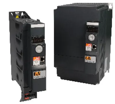 Available on requestB&R 8I76T401100.00-000 – Base device for ACOPOSinverter P76 and P74new
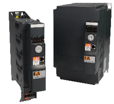 Available on requestB&R 8I76T401500.00-000 – Base device for ACOPOSinverter P76 and P74new
 Available on requestB&R 8I77S100025.0P-000 – ACOPOSinverter P77, 1x 90-132 V; 0.25 kW (heavy duty)Available on requestB&R 8I77S100037.0P-000 – ACOPOSinverter P77, 1x 90-132 V; 0.37 kW (heavy duty)Available on requestB&R 8I77S100110.0P-000 – ACOPOSinverter P77, 1x 90-132 V; 1.1 kW (heavy duty)Available on requestB&R 8I77S200025.0P-000 – ACOPOSinverter P77, 1x 170-264 V; 0.25 kW (heavy duty)Available on requestB&R 8I77S200037.0P-000 – ACOPOSinverter P77, 1x 170-264 V; 0.37 kW (heavy duty)Available on requestB&R 8I77S200055.0P-000 – ACOPOSinverter P77, 1x 170-264 V; 0.55 kW (heavy duty)