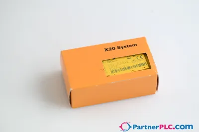
B&R X20DS1119
見積もりを依頼する



基本情報
| 在庫状況 | お問い合わせにより確認 |
| カテゴリー | Digital signal processing and preparation |
| ライフサイクル | active |
| 保証 | 12か月(新品)・3か月(中古・整備済み) |
配送・在庫状況
X20DS1119はいつ発送できますか?
X20DS1119はお問い合わせにより調達いたします — 見積もりを依頼いただければ、この個体の正確な在庫状況と配送スケジュールをご案内いたします。
X20DS1119を直接引き取ることはできますか?
オランダ・フローニンゲンの当社倉庫での引き取りが可能な場合があります — ご注文前にお問い合わせいただき、在庫状況と引き取り日時をご確認ください。
エクスプレス配送は利用できますか?
はい — X20DS1119の見積もり依頼時にその旨をお知らせいただければ、返信にエクスプレス配送のオプションを含めてご案内いたします。
工場が停止しており緊急で必要です — 対応可能ですか?
重大な故障の場合は、+31 (0)50-7110348またはsales@partnerplc.comまで直接ご連絡ください — X20DS1119について、在庫状況と配送先に応じて即日クーリエまたは専用タクシー・ホットショット配送を検討いたします。
3 digital 5 V channels, configurable as inputs or outputs2 digital 24 V input channels1 universal counter pair (2 event counters, AB counters or up/down counters)Linear motion generator (A/B, direction/frequency) with one reference pulseSSI absolute encoderNetTime timestamp: Input data, target position, position change, edge change, counter change This module is a multifunction digital signal processor module. It can be used extremely flexibly for a wide variety of tasks involving digital signal processing or digital signal generation. Two primary example applications include controlling stepper output stages with pulse and direction signals or using as encoder emulation. In this application, for example, frequency inverters or servo axes with the speed follow function can follow a real or virtual master axis. An additional major feature is the module's integrated timestamp function. It allows counter ramps curves to be generated virtually independently of bus cycle times during encoder emulation, for example. Only the target counter value and moment when it should be reached are transferred. The module automatically generates the corresponding counter values at the appropriate time, precisely in microsecond resolution and independently of the bus clock.
仕様
Specifications
| I/O module | 3 digital 5 V (symmetrical) channels configurable as inputs or outputs, 2 digital 24 V (asymmetrical) input channels, 1 universal counter pair (2 event counters, AB counter or up/down counter), linear motion generator (A/B, direction/frequency) with 1 reference pulse, SSI absolute encoder, relative or absolute moments of input edges with microsecond resolution, time-triggered I/O, I/O oversampling |
| B&R ID code | 0xA067 |
| Status indicators | I/O function per channel, operating state, module status |
| Module run/error | Yes, using LED status indicator and software |
| Inputs/Outputs | Yes, using LED status indicator |
| Bus | 0.01 W |
| Internal I/O | 1.5 W |
| Additional power dissipation caused by actuators (resistive) [W] | - |
| Type of signal lines | Shielded lines must be used for all signal lines. |
| CE | Yes |
| UKCA | Yes |
| CRA (Cyber Resilience Act) | In preparation |
| ATEX | Zone 2, II 3G Ex nA nC IIA T5 GcIP20, Ta (see X20 user's manual)FTZÚ 09 ATEX 0083X |
| UL | cULus E115267Industrial control equipment |
| HazLoc | cCSAus 244665Process control equipmentfor hazardous locations Class I, Division 2, Groups ABCD, T5 |
| DNV | Temperature: B (0 to 55°C)Humidity: B (up to 100%)Vibration: B (4 g)EMC: B (bridge and open deck) |
| CCS | Yes |
| LR | ENV1 |
| KR | Yes |
| ABS | Yes |
| BV | EC33BTemperature: 5 - 55°CVibration: 4 gEMC: Bridge and open deck |
| KC | Yes |
| Quantity | Up to 3, configuration as input or output using software |
| Encoder outputs | 5 V, symmetrical (A/B, direction/frequency) |
| Counter size | 16/32-bit |
| Max. transfer rate | 1 Mbit/s |
| Encoder signal | 5 V, symmetrical |
| 5 VDC | ±5%, module-internal, max. 300 mA |
| 24 VDC | Module-internal, max. 300 mA |
| Nominal voltage | 5 VDC |
| Input characteristics per EN 61131-2 | Type 1 |
| Input frequency | Max. 600 kHz |
| Common-mode range | -7 V ≤ VCM ≤ +12 V |
| Insulation voltage between encoder and bus | 500 Veff |
| Overload characteristics of encoder power supply | Short-circuit proof, overload-proof |
| Hardware | ≤2 µs |
| Software | - |
| Additional functions | SSI absolute encoder, linear motion generator |
| Input circuit | Sink |
| Input voltage | 24 VDC -15% / +20% |
| Input current at 24 VDC | Approx. 3.4 mA |
| Input resistance | Approx. 7.19 kΩ |
| Low | <5 VDC |
| High | >15 VDC |
| Insulation voltage between channel and bus | 500 Veff |
| Operating modes | 2x event counter, up/down counter, AB counter |
| Encoder inputs | 5 V, symmetrical |
| AB counter | 4x |
| Event counters | 2x |
| Up/Down counter | 2x |
| Type | 5 VDC differential signal, EiA RS485 standard |
| Output circuit | Sink and/or source |
| Output protection | Short-circuit protection |
| Variant | Push/Pull/Push-Pull |
| Output current | Max. 65 mA |
| Diagnostic status | Output is readable. |
| Switching frequency | Max. 500 kHz |
| Switching voltage | 5 VDC differential signal, EiA RS485 standard |
| Electrical isolation | Channel isolated from busChannel not isolated from channel |
| Horizontal | Yes |
| Vertical | Yes |
| 0 to 2000 m | No limitation |
| >2000 m | Reduction of ambient temperature by 0.5°C per 100 m |
| Degree of protection per EN 60529 | IP20 |
| Horizontal mounting orientation | -25 to 60°C |
| Vertical mounting orientation | -25 to 50°C |
| Derating | - |
| Storage | 5 to 95%, non-condensing |
| Transport | 5 to 95%, non-condensing |
| Operation | 5 to 95%, non-condensing |
| Note | Order 1x terminal block X20TB12 separately.Order 1x bus module X20BM11 separately. |
| Pitch | 12.5+0.2 mm |