


Pepperl Fuchs HiC2822
Angebot anfordern



Kurzübersicht
| Verfügbarkeit | Bestätigung auf Anfrage |
| Kategorie | H-System (Termination Board Mounting) |
| Lebenszyklus | active |
| Garantie | 12 Monate (neu) · 3 Monate (gebraucht/aufbereitet) |
Versand & Verfügbarkeit
Wann kann HiC2822 versendet werden?
HiC2822 wird auf Anfrage beschafft — fordern Sie ein Angebot an, wir bestätigen die genaue Verfügbarkeit und Lieferzeit für dieses konkrete Teil.
Kann ich HiC2822 persönlich abholen?
Eine Abholung in unserem Lager in Groningen, Niederlande ist eventuell möglich — kontaktieren Sie uns vor der Bestellung, um Verfügbarkeit und einen Abholtermin zu klären.
Ist Expressversand verfügbar?
Ja — erwähnen Sie es bei Ihrer Angebotsanfrage für HiC2822, wir nennen Ihnen in unserer Antwort die Expressversandoptionen.
Unser Betrieb steht still und wir brauchen es dringend — können Sie helfen?
Bei einem kritischen Ausfall kontaktieren Sie uns direkt unter +31 (0)50-7110348 oder sales@partnerplc.com — wir prüfen dann Same-Day-Kurier- oder Taxi-/Hotshot-Lieferung für HiC2822, abhängig von Verfügbarkeit und Zielort.
Switch Amplifier. 2-channel isolated barrier, 24 V DC supply (bus powered), Dry contact or NAMUR inputs, 2 relay contact outputs, Line fault detection (LFD), Reversible mode of operation, Up to SIL 2 acc. to IEC/EN 61508, Housing width: 12.5 mm, Number of channels: 2-channel, Safety Integrity Level (SIL): SIL 2, Rated voltage: 19 ... 30 V DC bus powered via Termination Board, Field device: NAMUR sensor, Field device [2]: volt-free contact, Line fault detection, Type: 2 x relay (NO contact), Fault indication output. Signal type: Digital Input. Safety Integrity Level (SIL): SIL 2. Connection: SL1: 1a(-), 1b(-); 2a(+), 2b(+). Rated voltage: 19 ... 30 V DC bus powered via Termination Board. Ripple: ≤ 10 %. Rated current: ≤ 30 mA. Power dissipation: ≤ 600 mW. Power consumption: ≤ 600 mW. Connection side: field side. Connection: SL2: 5a(+), 5b(-); 1a(+), 1b(-). Rated values: acc. to EN 60947-5-6 (NAMUR), see manual for electrical data. Open circuit voltage/short-circuit current: approx. 10 V DC / approx. 8 mA. Switching point/switching hysteresis: 1.2 ... 2.1 mA / approx. 0.2 mA. Line fault detection: breakage I ≤ 0.1 mA , short-circuit I ≥ 6.7 mA. Pulse/Pause ratio: min. 20 ms / min. 20 ms. Connection side: control side. Connection: SL1: 8a, 7a; 10a, 9a. Output I: signal ; relay. Output II: signal ; relay. Contact loading: 50 V DC / 0.5 A. Minimum switch current: 2 mA / 24 V DC. Energized/De-energized delay: ≤ 20 ms / ≤ 20 ms. Mechanical life: 107 switching cycles. Connection: SL1: 6b. Output type: open collector transistor (internal fault bus). Switching frequency: ≤ 10 Hz. Output/power supply: basic insulation acc. to EN 50178, rated insulation voltage of 50 V AC. Output/Output: basic insulation acc. to EN 50178, rated insulation voltage of 50 V AC. Display elements: LEDs. Control elements: DIP switch. Configuration: via DIP switches. Labeling: space for labeling at the front. Electromagnetic compatibility: . Directive 2014/30/EUEN 61326-1:2013 (industrial locations): . Directive 2014/30/EU: EN 61326-1:2013 (industrial locations). Galvanic isolation: EN 50178:1997. Electromagnetic compatibility: EN IEC 61326-3-2:2018 , NE 21:2012For further information see system description.. Degree of protection: IEC 60529:2001. Input: EN 60947-5-6:2000. Ambient temperature: -20 ... 60 °C (-4 ... 140 °F). Degree of protection: IP20. Mass: approx. 110 g. Dimensions: 12.5 x 106 x 128 mm (0.5 x 4.2 x 5.1 inch) (W x H x D). Height106 mmWidth12.5 mmDepth128 mm: . Height: 106 mm. Width: 12.5 mm. Depth: 128 mm. Mounting: on termination board. Coding: pin 1 and 2 trimmed For further information see system description.. EU-type examination certificate: BASEEFA 06 ATEX 0093 X. Marking II (1)G [Ex ia Ga] IIC [exsign] II (1)D [Ex ia Da] IIIC [exsign] I (M1) [Ex ia Ma] IInput[Ex ia Ga] IIC, [Ex ia Da] IIIC, [Ex ia Ma] IVoltageUo10.5 VCurrentIo17.1 mAPowerPo45 mW (linear characteristic): . Marking: II (1)G [Ex ia Ga] IIC [exsign] II (1)D [Ex ia Da] IIIC [exsign] I (M1) [Ex ia Ma] I. Input: [Ex ia Ga] IIC, [Ex ia Da] IIIC, [Ex ia Ma] I. Voltage: 10.5 V. Current: 17.1 mA. Power: 45 mW (linear characteristic). Supply: . Maximum safe voltageUm253 V AC (Attention! Um is no rated voltage.): Um. Maximum safe voltage: 253 V AC (Attention! Um is no rated voltage.). Output: . Contact loading50 V DC / 0.5 AMaximum safe voltageUm253 V AC (Attention! The rated voltage can be lower.): . Contact loading: 50 V DC / 0.5 A. Maximum safe voltage: 253 V AC (Attention! The rated voltage can be lower.). Certificate: PF 08 CERT 1047 X. Marking II 3G Ex nA nC IIC T4 Gc: . Marking: II 3G Ex nA nC IIC T4 Gc. Galvanic isolation: . Input/Outputsafe electrical isolation acc. to IEC/EN 60079-11, voltage peak value 375 VInput/power supplysafe electrical isolation acc. to IEC/EN 60079-11, voltage peak value 375 V: . Input/Output: safe electrical isolation acc. to IEC/EN 60079-11, voltage peak value 375 V. Input/power supply: safe electrical isolation acc. to IEC/EN 60079-11, voltage peak value 375 V. Directive conformity: . Directive 2014/34/EUEN IEC 60079-0:2018+AC:2020 , EN 60079-11:2012 , EN 60079-15:2010: . Directive 2014/34/EU: EN IEC 60079-0:2018+AC:2020 , EN 60079-11:2012 , EN 60079-15:2010. FM approval: . Control drawing16-534FM-12 (cFMus): . Control drawing: 16-534FM-12 (cFMus). UL approval: E106378. Control drawing116-0434: . Control drawing: 116-0434. IECEx approval: . IECEx certificateIECEx BAS 06.0026XIECEx marking[Ex ia Ga] IIC [Ex ia Da] IIIC [Ex ia Ma] I: . IECEx certificate: IECEx BAS 06.0026X. IECEx marking: [Ex ia Ga] IIC [Ex ia Da] IIIC [Ex ia Ma] I. Supplementary information: Observe the certificates, declarations of conformity, instruction manuals, and manuals where applicable. For information see www.pepperl-fuchs.com.
Spezifikationen
General specifications
| Signal type | Digital Input |
Functional safety related parameters
| Safety Integrity Level (SIL) | SIL 2 |
Supply
| Connection | SL1: 1a(-), 1b(-); 2a(+), 2b(+) |
| Rated voltage | 19 ... 30 V DC bus powered via Termination Board Ur |
| Ripple | ≤ 10 % |
| Rated current | ≤ 30 mA Ir |
| Power dissipation | ≤ 600 mW |
| Power consumption | ≤ 600 mW |
Input
| Connection side | field side |
| Connection | SL2: 5a(+), 5b(-); 1a(+), 1b(-) |
| Rated values | acc. to EN 60947-5-6 (NAMUR), see manual for electrical data |
| Open circuit voltage/short-circuit current | approx. 10 V DC / approx. 8 mA |
| Switching point/switching hysteresis | 1.2 ... 2.1 mA / approx. 0.2 mA |
| Line fault detection | breakage I ≤ 0.1 mA , short-circuit I ≥ 6.7 mA |
| Pulse/Pause ratio | min. 20 ms / min. 20 ms |
Output
| Connection side | control side |
| Connection | SL1: 8a, 7a; 10a, 9a |
| Output I | signal ; relay |
| Output II | signal ; relay |
| Contact loading | 50 V DC / 0.5 A |
| Minimum switch current | 2 mA / 24 V DC |
| Energized/De-energized delay | ≤ 20 ms / ≤ 20 ms |
| Mechanical life | 107 switching cycles |
Fault indication output
| Connection | SL1: 6b |
| Output type | open collector transistor (internal fault bus) |
Transfer characteristics
| Switching frequency | ≤ 10 Hz |
Galvanic isolation
| Output/power supply | basic insulation acc. to EN 50178, rated insulation voltage of 50 V AC |
| Output/Output | basic insulation acc. to EN 50178, rated insulation voltage of 50 V AC |
Indicators/settings
| Display elements | LEDs |
| Control elements | DIP switch |
| Configuration | via DIP switches |
| Labeling | space for labeling at the front |
Directive conformity
| Electromagnetic compatibility | |
| Directive 2014/30/EUEN 61326-1:2013 (industrial locations) | Directive 2014/30/EU |
| Directive 2014/30/EU | EN 61326-1:2013 (industrial locations) |
Conformity
| Galvanic isolation | EN 50178:1997 |
| Electromagnetic compatibility | EN IEC 61326-3-2:2018 , NE 21:2012For further information see system description. |
| Degree of protection | IEC 60529:2001 |
| Input | EN 60947-5-6:2000 |
Ambient conditions
| Ambient temperature | -20 ... 60 °C (-4 ... 140 °F) |
Mechanical specifications
| Degree of protection | IP20 |
| Mass | approx. 110 g |
| Dimensions | 12.5 x 106 x 128 mm (0.5 x 4.2 x 5.1 inch) (W x H x D) |
| Height106 mmWidth12.5 mmDepth128 mm | Height |
| Height | 106 mm |
| Width | 12.5 mm |
| Depth | 128 mm |
| Mounting | on termination board |
| Coding | pin 1 and 2 trimmed For further information see system description. |
Data for application in connection with hazardous areas
| EU-type examination certificate | BASEEFA 06 ATEX 0093 X |
| Marking II (1)G [Ex ia Ga] IIC [exsign] II (1)D [Ex ia Da] IIIC [exsign] I (M1) [Ex ia Ma] IInput[Ex ia Ga] IIC, [Ex ia Da] IIIC, [Ex ia Ma] IVoltageUo10.5 VCurrentIo17.1 mAPowerPo45 mW (linear characteristic) | Marking |
| Marking | II (1)G [Ex ia Ga] IIC [exsign] II (1)D [Ex ia Da] IIIC [exsign] I (M1) [Ex ia Ma] I |
| Input | [Ex ia Ga] IIC, [Ex ia Da] IIIC, [Ex ia Ma] I |
| Voltage | 10.5 V Uo |
| Current | 17.1 mA Io |
| Power | 45 mW (linear characteristic) Po |
| Supply | |
| Maximum safe voltageUm253 V AC (Attention! Um is no rated voltage.) | Um Maximum safe voltage |
| Maximum safe voltage | 253 V AC (Attention! Um is no rated voltage.) Um |
| Output | |
| Contact loading50 V DC / 0.5 AMaximum safe voltageUm253 V AC (Attention! The rated voltage can be lower.) | Contact loading |
| Contact loading | 50 V DC / 0.5 A |
| Maximum safe voltage | 253 V AC (Attention! The rated voltage can be lower.) Um |
| Certificate | PF 08 CERT 1047 X |
| Marking II 3G Ex nA nC IIC T4 Gc | Marking |
| Marking | II 3G Ex nA nC IIC T4 Gc |
| Galvanic isolation | |
| Input/Outputsafe electrical isolation acc. to IEC/EN 60079-11, voltage peak value 375 VInput/power supplysafe electrical isolation acc. to IEC/EN 60079-11, voltage peak value 375 V | Input/Output |
| Input/Output | safe electrical isolation acc. to IEC/EN 60079-11, voltage peak value 375 V |
| Input/power supply | safe electrical isolation acc. to IEC/EN 60079-11, voltage peak value 375 V |
| Directive conformity | |
| Directive 2014/34/EUEN IEC 60079-0:2018+AC:2020 , EN 60079-11:2012 , EN 60079-15:2010 | Directive 2014/34/EU |
| Directive 2014/34/EU | EN IEC 60079-0:2018+AC:2020 , EN 60079-11:2012 , EN 60079-15:2010 |
International approvals
| FM approval | |
| Control drawing16-534FM-12 (cFMus) | Control drawing |
| Control drawing | 16-534FM-12 (cFMus) |
| UL approval | E106378 |
| Control drawing116-0434 | Control drawing |
| Control drawing | 116-0434 |
| IECEx approval | |
| IECEx certificateIECEx BAS 06.0026XIECEx marking[Ex ia Ga] IIC [Ex ia Da] IIIC [Ex ia Ma] I | IECEx certificate |
| IECEx certificate | IECEx BAS 06.0026X |
| IECEx marking | [Ex ia Ga] IIC [Ex ia Da] IIIC [Ex ia Ma] I |
General information
| Supplementary information | Observe the certificates, declarations of conformity, instruction manuals, and manuals where applicable. For information see www.pepperl-fuchs.com. |
Weitere Pepperl Fuchs-Teile
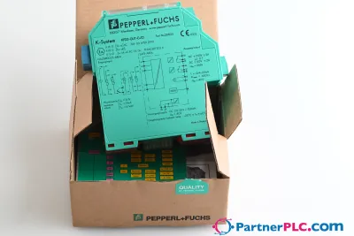 NeuPepperl + Fuchs KFD2-GUT-EX1.D New open box
 Auf Anfrage erhältlichPepperl Fuchs V19-W-BK15M-PUR-U-V19-G
 Auf Anfrage erhältlichPepperl Fuchs V1SD-G-GN65M-PUR-E1S-V45-G