


Pepperl Fuchs FB3202B2
Angebot anfordern



Kurzübersicht
| Verfügbarkeit | Bestätigung auf Anfrage |
| Kategorie | FB (Zone 1) |
| Lebenszyklus | active |
| Garantie | 12 Monate (neu) · 3 Monate (gebraucht/aufbereitet) |
Versand & Verfügbarkeit
Wann kann FB3202B2 versendet werden?
FB3202B2 wird auf Anfrage beschafft — fordern Sie ein Angebot an, wir bestätigen die genaue Verfügbarkeit und Lieferzeit für dieses konkrete Teil.
Kann ich FB3202B2 persönlich abholen?
Eine Abholung in unserem Lager in Groningen, Niederlande ist eventuell möglich — kontaktieren Sie uns vor der Bestellung, um Verfügbarkeit und einen Abholtermin zu klären.
Ist Expressversand verfügbar?
Ja — erwähnen Sie es bei Ihrer Angebotsanfrage für FB3202B2, wir nennen Ihnen in unserer Antwort die Expressversandoptionen.
Unser Betrieb steht still und wir brauchen es dringend — können Sie helfen?
Bei einem kritischen Ausfall kontaktieren Sie uns direkt unter +31 (0)50-7110348 oder sales@partnerplc.com — wir prüfen dann Same-Day-Kurier- oder Taxi-/Hotshot-Lieferung für FB3202B2, abhängig von Verfügbarkeit und Zielort.
HART Transmitter Power Supply, Input Isolator. 1-channel, Input Ex ia, Power supply for 2- or 3-wire transmitters with 4 mA ... 20 mA, Module can be exchanged under voltage (hot swap), Explosion protection: Ex ia, Field device: pressure converter, Field device [2]: flow converter, Field device [3]: level converter, Field device [4]: Temperature Converter, Connection: 2-wire transmitter, Connection [2]: 3-wire transmitter, Connection [3]: 4-wire transmitter, HART communication. Occupied slots: 1. Connection: backplane bus. Rated voltage: 12 V DC , only in connection with the power supplies FB92**. Power dissipation: 0.75 W. Power consumption: 1.1 W. Connection: backplane bus. Interface: manufacturer-specific bus to standard com unit. Number of channels: 1. Suitable field devices: . Field devicepressure converterField device [2]flow converterField device [3]level converterField device [4]Temperature Converter: . Field device: pressure converter. Field device [2]: flow converter. Field device [3]: level converter. Field device [4]: Temperature Converter. Field device interface: . Connection2-wire transmitterConnection [2]3-wire transmitterConnection [3]4-wire transmitter: . Connection: 2-wire transmitter. Connection [2]: 3-wire transmitter. Connection [3]: 4-wire transmitter. Connection: 2-wire transmitter (HART):supply circuit: 2/3+, 4/5-3-wire transmitter (HART):supply circuit: 2/3+, 6-measuring circuit: 4/5+, 6-4-wire transmitter (separately powered):measuring circuit: 4/5+, 6-HART measuring circuit: 1+, 6-. Transmitter supply voltage: min. 15 V at 20 mA ; 21.5 V at 4 mA. Input resistance: 15 Ω (terminals 5, 6) 236 Ω (terminals 1, 6) HART. Line fault detection: can be switched on/off for each channel via configuration tool , configurable via configuration tool. Short-circuitfactory setting: > 22 mA configurable between 0 ... 26 mAOpen-circuitfactory setting: < 1 mA configurable between 0 ... 26 mA: . Short-circuit: factory setting: > 22 mA configurable between 0 ... 26 mA. Open-circuit: factory setting: < 1 mA configurable between 0 ... 26 mA. HART communication: yes. HART secondary variable: yes. Deviation: . After calibration0.1 % of the signal range at 20 °C (68 °F)Influence of ambient temperature0.1 %/10 K of the signal range: . After calibration: 0.1 % of the signal range at 20 °C (68 °F). Influence of ambient temperature: 0.1 %/10 K of the signal range. Resolution: 12 Bit (0 ... 26 mA). Refresh time: 100 ms. LED indication: Power LED (P) green: supply Diagnostic LED (I) red: module fault , red flashing: communication error , white: fixed parameter set (parameters from com unit are ignored) , white flashing: requests parameters from com unit Status LED (1) red: line fault (lead breakage or short circuit) Status LED (2) yellow: Live Zero monitoring. Coding: optional mechanical coding via front socket. Electromagnetic compatibility: . Directive 2014/30/EUEN 61326-1:2013: . Directive 2014/30/EU: EN 61326-1:2013. Electromagnetic compatibility: NE 21:2007. Degree of protection: IEC 60529:2000. Environmental test: EN 60068-2-14:2009. Shock resistance: EN 60068-2-27:2009. Vibration resistance: EN 60068-2-6:2008. Damaging gas: EN 60068-2-42:2003. Relative humidity: EN 60068-2-78:2001. Ambient temperature: -20 ... 60 °C (-4 ... 140 °F). Storage temperature: -25 ... 85 °C (-13 ... 185 °F). Relative humidity: 95 % non-condensing. Shock resistance: shock type I, shock duration 11 ms, shock amplitude 15 g, number of shocks 18. Vibration resistance: frequency range 10 ... 150 Hz; transition frequency: 57.56 Hz, amplitude/acceleration ± 0.075 mm/1 g; 10 cyclesfrequency range 5 ... 100 Hz; transition frequency: 13.2 Hz amplitude/acceleration ± 1 mm/0.7 g; 90 minutes at each resonance. Damaging gas: designed for operation in environmental conditions acc. to ISA-S71.04-1985, severity level G3. Degree of protection: IP20 (module) , a separate housing is required acc. to the system description. Connection: removable front connector with screw flange (accessory)wiring connection via spring terminals (0.14 ... 1.5 mm2) or screw terminals (0.08 ... 1.5 mm2). Mass: approx. 350 g. Dimensions: . Height107 mmWidth28 mmDepth132 mm: . Height: 107 mm. Width: 28 mm. Depth: 132 mm. EU-type examination certificate: BVS 13 ATEX E 050 X. Marking II 2(1) G Ex d [ia Ga] IIC T4 Gb[exsign] II (1) D [Ex ia Da] IIIC: . Marking: II 2(1) G Ex d [ia Ga] IIC T4 Gb[exsign] II (1) D [Ex ia Da] IIIC. Supply: . VoltageUo27 VCurrentIo92 mAPowerPo619 mW (linear characteristic): Uo. Voltage: 27 V. Current: 92 mA. Power: 619 mW (linear characteristic). Connection 1 to 6: . Voltage8.9 VCurrent4 mAPower24 mW (trapezoid characteristic curve): . Voltage: 8.9 V. Current: 4 mA. Power: 24 mW (trapezoid characteristic curve). Input: . VoltageUo0.7 VCurrentIo7 mAPowerPo5 mW (trapezoid characteristic curve)VoltageUi30 V DCCurrentIi100 mAPowerPi100 mW Pi < 100 mW is fulfilled by Ii < 100 mA, so a comparison of Po < Pi is not necessary.Internal capacitanceCi242 nFInternal inductanceLi0 mH: Uo. Voltage: 0.7 V. Current: 7 mA. Power: 5 mW (trapezoid characteristic curve). Voltage: 30 V DC. Current: 100 mA. Power: 100 mW Pi < 100 mW is fulfilled by Ii < 100 mA, so a comparison of Po < Pi is not necessary.. Internal capacitance: 242 nF. Internal inductance: 0 mH. Galvanic isolation: . Input/power supply, internal bussafe electrical isolation acc. to EN 60079-11:2007 , voltage peak value 375 V: . Input/power supply, internal bus: safe electrical isolation acc. to EN 60079-11:2007 , voltage peak value 375 V. Directive conformity: . Directive 2014/34/EUEN IEC 60079-0:2018+AC:2020 EN 60079-1:2014 EN 60079-11:2012: . Directive 2014/34/EU: EN IEC 60079-0:2018+AC:2020 EN 60079-1:2014 EN 60079-11:2012. ATEX approval: BVS 13 ATEX E 050 X. System information: The module has to be mounted in appropriate backplanes and housings (FB92**) in Zone 1, 2, 21, 22 or outside hazardous areas (gas or dust). Here, observe the corresponding EC-type examination certificate.. Supplementary information: EC-Type Examination Certificate, Statement of Conformity, Declaration of Conformity, Attestation of Conformity and instructions have to be observed where applicable. For information see www.pepperl-fuchs.com.
Spezifikationen
Slots
| Occupied slots | 1 |
Supply
| Connection | backplane bus |
| Rated voltage | 12 V DC , only in connection with the power supplies FB92** Ur |
| Power dissipation | 0.75 W |
| Power consumption | 1.1 W |
Internal bus
| Connection | backplane bus |
| Interface | manufacturer-specific bus to standard com unit |
Analog input
| Number of channels | 1 |
| Suitable field devices | |
| Field devicepressure converterField device [2]flow converterField device [3]level converterField device [4]Temperature Converter | Field device |
| Field device | pressure converter |
| Field device [2] | flow converter |
| Field device [3] | level converter |
| Field device [4] | Temperature Converter |
| Field device interface | |
| Connection2-wire transmitterConnection [2]3-wire transmitterConnection [3]4-wire transmitter | Connection |
| Connection | 2-wire transmitter |
| Connection [2] | 3-wire transmitter |
| Connection [3] | 4-wire transmitter |
| Connection | 2-wire transmitter (HART):supply circuit: 2/3+, 4/5-3-wire transmitter (HART):supply circuit: 2/3+, 6-measuring circuit: 4/5+, 6-4-wire transmitter (separately powered):measuring circuit: 4/5+, 6-HART measuring circuit: 1+, 6- |
| Transmitter supply voltage | min. 15 V at 20 mA ; 21.5 V at 4 mA |
| Input resistance | 15 Ω (terminals 5, 6) 236 Ω (terminals 1, 6) HART |
| Line fault detection | can be switched on/off for each channel via configuration tool , configurable via configuration tool |
| Short-circuitfactory setting: > 22 mA configurable between 0 ... 26 mAOpen-circuitfactory setting: < 1 mA configurable between 0 ... 26 mA | Short-circuit |
| Short-circuit | factory setting: > 22 mA configurable between 0 ... 26 mA |
| Open-circuit | factory setting: < 1 mA configurable between 0 ... 26 mA |
| HART communication | yes |
| HART secondary variable | yes |
Transfer characteristics
| Deviation | |
| After calibration0.1 % of the signal range at 20 °C (68 °F)Influence of ambient temperature0.1 %/10 K of the signal range | After calibration |
| After calibration | 0.1 % of the signal range at 20 °C (68 °F) |
| Influence of ambient temperature | 0.1 %/10 K of the signal range |
| Resolution | 12 Bit (0 ... 26 mA) |
| Refresh time | 100 ms |
Indicators/settings
| LED indication | Power LED (P) green: supply Diagnostic LED (I) red: module fault , red flashing: communication error , white: fixed parameter set (parameters from com unit are ignored) , white flashing: requests parameters from com unit Status LED (1) red: line fault (lead breakage or short circuit) Status LED (2) yellow: Live Zero monitoring |
| Coding | optional mechanical coding via front socket |
Directive conformity
| Electromagnetic compatibility | |
| Directive 2014/30/EUEN 61326-1:2013 | Directive 2014/30/EU |
| Directive 2014/30/EU | EN 61326-1:2013 |
Conformity
| Electromagnetic compatibility | NE 21:2007 |
| Degree of protection | IEC 60529:2000 |
| Environmental test | EN 60068-2-14:2009 |
| Shock resistance | EN 60068-2-27:2009 |
| Vibration resistance | EN 60068-2-6:2008 |
| Damaging gas | EN 60068-2-42:2003 |
| Relative humidity | EN 60068-2-78:2001 |
Ambient conditions
| Ambient temperature | -20 ... 60 °C (-4 ... 140 °F) |
| Storage temperature | -25 ... 85 °C (-13 ... 185 °F) |
| Relative humidity | 95 % non-condensing |
| Shock resistance | shock type I, shock duration 11 ms, shock amplitude 15 g, number of shocks 18 |
| Vibration resistance | frequency range 10 ... 150 Hz; transition frequency: 57.56 Hz, amplitude/acceleration ± 0.075 mm/1 g; 10 cyclesfrequency range 5 ... 100 Hz; transition frequency: 13.2 Hz amplitude/acceleration ± 1 mm/0.7 g; 90 minutes at each resonance |
| Damaging gas | designed for operation in environmental conditions acc. to ISA-S71.04-1985, severity level G3 |
Mechanical specifications
| Degree of protection | IP20 (module) , a separate housing is required acc. to the system description |
| Connection | removable front connector with screw flange (accessory)wiring connection via spring terminals (0.14 ... 1.5 mm2) or screw terminals (0.08 ... 1.5 mm2) |
| Mass | approx. 350 g |
| Dimensions | |
| Height107 mmWidth28 mmDepth132 mm | Height |
| Height | 107 mm |
| Width | 28 mm |
| Depth | 132 mm |
Data for application in connection with hazardous areas
| EU-type examination certificate | BVS 13 ATEX E 050 X |
| Marking II 2(1) G Ex d [ia Ga] IIC T4 Gb[exsign] II (1) D [Ex ia Da] IIIC | Marking |
| Marking | II 2(1) G Ex d [ia Ga] IIC T4 Gb[exsign] II (1) D [Ex ia Da] IIIC |
| Supply | |
| VoltageUo27 VCurrentIo92 mAPowerPo619 mW (linear characteristic) | Uo Voltage |
| Voltage | 27 V Uo |
| Current | 92 mA Io |
| Power | 619 mW (linear characteristic) Po |
| Connection 1 to 6 | |
| Voltage8.9 VCurrent4 mAPower24 mW (trapezoid characteristic curve) | Voltage |
| Voltage | 8.9 V |
| Current | 4 mA |
| Power | 24 mW (trapezoid characteristic curve) |
| Input | |
| VoltageUo0.7 VCurrentIo7 mAPowerPo5 mW (trapezoid characteristic curve)VoltageUi30 V DCCurrentIi100 mAPowerPi100 mW Pi < 100 mW is fulfilled by Ii < 100 mA, so a comparison of Po < Pi is not necessary.Internal capacitanceCi242 nFInternal inductanceLi0 mH | Uo Voltage |
| Voltage | 0.7 V Uo |
| Current | 7 mA Io |
| Power | 5 mW (trapezoid characteristic curve) Po |
| Voltage | 30 V DC Ui |
| Current | 100 mA Ii |
| Power | 100 mW Pi < 100 mW is fulfilled by Ii < 100 mA, so a comparison of Po < Pi is not necessary. Pi |
| Internal capacitance | 242 nF Ci |
| Internal inductance | 0 mH Li |
| Galvanic isolation | |
| Input/power supply, internal bussafe electrical isolation acc. to EN 60079-11:2007 , voltage peak value 375 V | Input/power supply, internal bus |
| Input/power supply, internal bus | safe electrical isolation acc. to EN 60079-11:2007 , voltage peak value 375 V |
| Directive conformity | |
| Directive 2014/34/EUEN IEC 60079-0:2018+AC:2020 EN 60079-1:2014 EN 60079-11:2012 | Directive 2014/34/EU |
| Directive 2014/34/EU | EN IEC 60079-0:2018+AC:2020 EN 60079-1:2014 EN 60079-11:2012 |
International approvals
| ATEX approval | BVS 13 ATEX E 050 X |
General information
| System information | The module has to be mounted in appropriate backplanes and housings (FB92**) in Zone 1, 2, 21, 22 or outside hazardous areas (gas or dust). Here, observe the corresponding EC-type examination certificate. |
| Supplementary information | EC-Type Examination Certificate, Statement of Conformity, Declaration of Conformity, Attestation of Conformity and instructions have to be observed where applicable. For information see www.pepperl-fuchs.com. |
Weitere Pepperl Fuchs-Teile
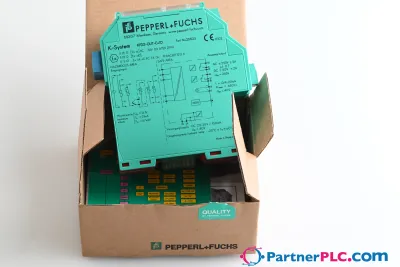 NeuPepperl + Fuchs KFD2-GUT-EX1.D New open box
 Auf Anfrage erhältlichPepperl Fuchs V19-W-BK15M-PUR-U-V19-G
 Auf Anfrage erhältlichPepperl Fuchs V1SD-G-GN65M-PUR-E1S-V45-G