


Pepperl Fuchs FB3202B2
Richiedi un preventivo



In breve
| Disponibilità | Conferma su richiesta |
| Categoria | FB (Zone 1) |
| Ciclo di vita | active |
| Garanzia | 12 mesi (nuovo) · 3 mesi (usato/rigenerato) |
Spedizione e disponibilità
Quando può essere spedito FB3202B2?
FB3202B2 viene reperito su richiesta — richiedi un preventivo e ti confermeremo disponibilità e tempi di consegna esatti per questa unità specifica.
Posso ritirare FB3202B2 di persona?
Il ritiro presso il nostro magazzino di Groningen, Paesi Bassi, potrebbe essere possibile — contattaci prima dell'ordine per verificare disponibilità e concordare un orario di ritiro.
È disponibile la consegna espressa?
Sì — menzionalo nella richiesta di preventivo per FB3202B2 e includeremo le opzioni di spedizione espressa nella nostra risposta.
Il nostro impianto è fermo e ci serve con urgenza: potete aiutarci?
In caso di guasto critico, contattaci direttamente al +31 (0)50-7110348 o a sales@partnerplc.com — valuteremo un corriere in giornata o una consegna dedicata per FB3202B2, in base a disponibilità e destinazione.
HART Transmitter Power Supply, Input Isolator. 1-channel, Input Ex ia, Power supply for 2- or 3-wire transmitters with 4 mA ... 20 mA, Module can be exchanged under voltage (hot swap), Explosion protection: Ex ia, Field device: pressure converter, Field device [2]: flow converter, Field device [3]: level converter, Field device [4]: Temperature Converter, Connection: 2-wire transmitter, Connection [2]: 3-wire transmitter, Connection [3]: 4-wire transmitter, HART communication. Occupied slots: 1. Connection: backplane bus. Rated voltage: 12 V DC , only in connection with the power supplies FB92**. Power dissipation: 0.75 W. Power consumption: 1.1 W. Connection: backplane bus. Interface: manufacturer-specific bus to standard com unit. Number of channels: 1. Suitable field devices: . Field devicepressure converterField device [2]flow converterField device [3]level converterField device [4]Temperature Converter: . Field device: pressure converter. Field device [2]: flow converter. Field device [3]: level converter. Field device [4]: Temperature Converter. Field device interface: . Connection2-wire transmitterConnection [2]3-wire transmitterConnection [3]4-wire transmitter: . Connection: 2-wire transmitter. Connection [2]: 3-wire transmitter. Connection [3]: 4-wire transmitter. Connection: 2-wire transmitter (HART):supply circuit: 2/3+, 4/5-3-wire transmitter (HART):supply circuit: 2/3+, 6-measuring circuit: 4/5+, 6-4-wire transmitter (separately powered):measuring circuit: 4/5+, 6-HART measuring circuit: 1+, 6-. Transmitter supply voltage: min. 15 V at 20 mA ; 21.5 V at 4 mA. Input resistance: 15 Ω (terminals 5, 6) 236 Ω (terminals 1, 6) HART. Line fault detection: can be switched on/off for each channel via configuration tool , configurable via configuration tool. Short-circuitfactory setting: > 22 mA configurable between 0 ... 26 mAOpen-circuitfactory setting: < 1 mA configurable between 0 ... 26 mA: . Short-circuit: factory setting: > 22 mA configurable between 0 ... 26 mA. Open-circuit: factory setting: < 1 mA configurable between 0 ... 26 mA. HART communication: yes. HART secondary variable: yes. Deviation: . After calibration0.1 % of the signal range at 20 °C (68 °F)Influence of ambient temperature0.1 %/10 K of the signal range: . After calibration: 0.1 % of the signal range at 20 °C (68 °F). Influence of ambient temperature: 0.1 %/10 K of the signal range. Resolution: 12 Bit (0 ... 26 mA). Refresh time: 100 ms. LED indication: Power LED (P) green: supply Diagnostic LED (I) red: module fault , red flashing: communication error , white: fixed parameter set (parameters from com unit are ignored) , white flashing: requests parameters from com unit Status LED (1) red: line fault (lead breakage or short circuit) Status LED (2) yellow: Live Zero monitoring. Coding: optional mechanical coding via front socket. Electromagnetic compatibility: . Directive 2014/30/EUEN 61326-1:2013: . Directive 2014/30/EU: EN 61326-1:2013. Electromagnetic compatibility: NE 21:2007. Degree of protection: IEC 60529:2000. Environmental test: EN 60068-2-14:2009. Shock resistance: EN 60068-2-27:2009. Vibration resistance: EN 60068-2-6:2008. Damaging gas: EN 60068-2-42:2003. Relative humidity: EN 60068-2-78:2001. Ambient temperature: -20 ... 60 °C (-4 ... 140 °F). Storage temperature: -25 ... 85 °C (-13 ... 185 °F). Relative humidity: 95 % non-condensing. Shock resistance: shock type I, shock duration 11 ms, shock amplitude 15 g, number of shocks 18. Vibration resistance: frequency range 10 ... 150 Hz; transition frequency: 57.56 Hz, amplitude/acceleration ± 0.075 mm/1 g; 10 cyclesfrequency range 5 ... 100 Hz; transition frequency: 13.2 Hz amplitude/acceleration ± 1 mm/0.7 g; 90 minutes at each resonance. Damaging gas: designed for operation in environmental conditions acc. to ISA-S71.04-1985, severity level G3. Degree of protection: IP20 (module) , a separate housing is required acc. to the system description. Connection: removable front connector with screw flange (accessory)wiring connection via spring terminals (0.14 ... 1.5 mm2) or screw terminals (0.08 ... 1.5 mm2). Mass: approx. 350 g. Dimensions: . Height107 mmWidth28 mmDepth132 mm: . Height: 107 mm. Width: 28 mm. Depth: 132 mm. EU-type examination certificate: BVS 13 ATEX E 050 X. Marking II 2(1) G Ex d [ia Ga] IIC T4 Gb[exsign] II (1) D [Ex ia Da] IIIC: . Marking: II 2(1) G Ex d [ia Ga] IIC T4 Gb[exsign] II (1) D [Ex ia Da] IIIC. Supply: . VoltageUo27 VCurrentIo92 mAPowerPo619 mW (linear characteristic): Uo. Voltage: 27 V. Current: 92 mA. Power: 619 mW (linear characteristic). Connection 1 to 6: . Voltage8.9 VCurrent4 mAPower24 mW (trapezoid characteristic curve): . Voltage: 8.9 V. Current: 4 mA. Power: 24 mW (trapezoid characteristic curve). Input: . VoltageUo0.7 VCurrentIo7 mAPowerPo5 mW (trapezoid characteristic curve)VoltageUi30 V DCCurrentIi100 mAPowerPi100 mW Pi < 100 mW is fulfilled by Ii < 100 mA, so a comparison of Po < Pi is not necessary.Internal capacitanceCi242 nFInternal inductanceLi0 mH: Uo. Voltage: 0.7 V. Current: 7 mA. Power: 5 mW (trapezoid characteristic curve). Voltage: 30 V DC. Current: 100 mA. Power: 100 mW Pi < 100 mW is fulfilled by Ii < 100 mA, so a comparison of Po < Pi is not necessary.. Internal capacitance: 242 nF. Internal inductance: 0 mH. Galvanic isolation: . Input/power supply, internal bussafe electrical isolation acc. to EN 60079-11:2007 , voltage peak value 375 V: . Input/power supply, internal bus: safe electrical isolation acc. to EN 60079-11:2007 , voltage peak value 375 V. Directive conformity: . Directive 2014/34/EUEN IEC 60079-0:2018+AC:2020 EN 60079-1:2014 EN 60079-11:2012: . Directive 2014/34/EU: EN IEC 60079-0:2018+AC:2020 EN 60079-1:2014 EN 60079-11:2012. ATEX approval: BVS 13 ATEX E 050 X. System information: The module has to be mounted in appropriate backplanes and housings (FB92**) in Zone 1, 2, 21, 22 or outside hazardous areas (gas or dust). Here, observe the corresponding EC-type examination certificate.. Supplementary information: EC-Type Examination Certificate, Statement of Conformity, Declaration of Conformity, Attestation of Conformity and instructions have to be observed where applicable. For information see www.pepperl-fuchs.com.
Specifiche
Slots
| Occupied slots | 1 |
Supply
| Connection | backplane bus |
| Rated voltage | 12 V DC , only in connection with the power supplies FB92** Ur |
| Power dissipation | 0.75 W |
| Power consumption | 1.1 W |
Internal bus
| Connection | backplane bus |
| Interface | manufacturer-specific bus to standard com unit |
Analog input
| Number of channels | 1 |
| Suitable field devices | |
| Field devicepressure converterField device [2]flow converterField device [3]level converterField device [4]Temperature Converter | Field device |
| Field device | pressure converter |
| Field device [2] | flow converter |
| Field device [3] | level converter |
| Field device [4] | Temperature Converter |
| Field device interface | |
| Connection2-wire transmitterConnection [2]3-wire transmitterConnection [3]4-wire transmitter | Connection |
| Connection | 2-wire transmitter |
| Connection [2] | 3-wire transmitter |
| Connection [3] | 4-wire transmitter |
| Connection | 2-wire transmitter (HART):supply circuit: 2/3+, 4/5-3-wire transmitter (HART):supply circuit: 2/3+, 6-measuring circuit: 4/5+, 6-4-wire transmitter (separately powered):measuring circuit: 4/5+, 6-HART measuring circuit: 1+, 6- |
| Transmitter supply voltage | min. 15 V at 20 mA ; 21.5 V at 4 mA |
| Input resistance | 15 Ω (terminals 5, 6) 236 Ω (terminals 1, 6) HART |
| Line fault detection | can be switched on/off for each channel via configuration tool , configurable via configuration tool |
| Short-circuitfactory setting: > 22 mA configurable between 0 ... 26 mAOpen-circuitfactory setting: < 1 mA configurable between 0 ... 26 mA | Short-circuit |
| Short-circuit | factory setting: > 22 mA configurable between 0 ... 26 mA |
| Open-circuit | factory setting: < 1 mA configurable between 0 ... 26 mA |
| HART communication | yes |
| HART secondary variable | yes |
Transfer characteristics
| Deviation | |
| After calibration0.1 % of the signal range at 20 °C (68 °F)Influence of ambient temperature0.1 %/10 K of the signal range | After calibration |
| After calibration | 0.1 % of the signal range at 20 °C (68 °F) |
| Influence of ambient temperature | 0.1 %/10 K of the signal range |
| Resolution | 12 Bit (0 ... 26 mA) |
| Refresh time | 100 ms |
Indicators/settings
| LED indication | Power LED (P) green: supply Diagnostic LED (I) red: module fault , red flashing: communication error , white: fixed parameter set (parameters from com unit are ignored) , white flashing: requests parameters from com unit Status LED (1) red: line fault (lead breakage or short circuit) Status LED (2) yellow: Live Zero monitoring |
| Coding | optional mechanical coding via front socket |
Directive conformity
| Electromagnetic compatibility | |
| Directive 2014/30/EUEN 61326-1:2013 | Directive 2014/30/EU |
| Directive 2014/30/EU | EN 61326-1:2013 |
Conformity
| Electromagnetic compatibility | NE 21:2007 |
| Degree of protection | IEC 60529:2000 |
| Environmental test | EN 60068-2-14:2009 |
| Shock resistance | EN 60068-2-27:2009 |
| Vibration resistance | EN 60068-2-6:2008 |
| Damaging gas | EN 60068-2-42:2003 |
| Relative humidity | EN 60068-2-78:2001 |
Ambient conditions
| Ambient temperature | -20 ... 60 °C (-4 ... 140 °F) |
| Storage temperature | -25 ... 85 °C (-13 ... 185 °F) |
| Relative humidity | 95 % non-condensing |
| Shock resistance | shock type I, shock duration 11 ms, shock amplitude 15 g, number of shocks 18 |
| Vibration resistance | frequency range 10 ... 150 Hz; transition frequency: 57.56 Hz, amplitude/acceleration ± 0.075 mm/1 g; 10 cyclesfrequency range 5 ... 100 Hz; transition frequency: 13.2 Hz amplitude/acceleration ± 1 mm/0.7 g; 90 minutes at each resonance |
| Damaging gas | designed for operation in environmental conditions acc. to ISA-S71.04-1985, severity level G3 |
Mechanical specifications
| Degree of protection | IP20 (module) , a separate housing is required acc. to the system description |
| Connection | removable front connector with screw flange (accessory)wiring connection via spring terminals (0.14 ... 1.5 mm2) or screw terminals (0.08 ... 1.5 mm2) |
| Mass | approx. 350 g |
| Dimensions | |
| Height107 mmWidth28 mmDepth132 mm | Height |
| Height | 107 mm |
| Width | 28 mm |
| Depth | 132 mm |
Data for application in connection with hazardous areas
| EU-type examination certificate | BVS 13 ATEX E 050 X |
| Marking II 2(1) G Ex d [ia Ga] IIC T4 Gb[exsign] II (1) D [Ex ia Da] IIIC | Marking |
| Marking | II 2(1) G Ex d [ia Ga] IIC T4 Gb[exsign] II (1) D [Ex ia Da] IIIC |
| Supply | |
| VoltageUo27 VCurrentIo92 mAPowerPo619 mW (linear characteristic) | Uo Voltage |
| Voltage | 27 V Uo |
| Current | 92 mA Io |
| Power | 619 mW (linear characteristic) Po |
| Connection 1 to 6 | |
| Voltage8.9 VCurrent4 mAPower24 mW (trapezoid characteristic curve) | Voltage |
| Voltage | 8.9 V |
| Current | 4 mA |
| Power | 24 mW (trapezoid characteristic curve) |
| Input | |
| VoltageUo0.7 VCurrentIo7 mAPowerPo5 mW (trapezoid characteristic curve)VoltageUi30 V DCCurrentIi100 mAPowerPi100 mW Pi < 100 mW is fulfilled by Ii < 100 mA, so a comparison of Po < Pi is not necessary.Internal capacitanceCi242 nFInternal inductanceLi0 mH | Uo Voltage |
| Voltage | 0.7 V Uo |
| Current | 7 mA Io |
| Power | 5 mW (trapezoid characteristic curve) Po |
| Voltage | 30 V DC Ui |
| Current | 100 mA Ii |
| Power | 100 mW Pi < 100 mW is fulfilled by Ii < 100 mA, so a comparison of Po < Pi is not necessary. Pi |
| Internal capacitance | 242 nF Ci |
| Internal inductance | 0 mH Li |
| Galvanic isolation | |
| Input/power supply, internal bussafe electrical isolation acc. to EN 60079-11:2007 , voltage peak value 375 V | Input/power supply, internal bus |
| Input/power supply, internal bus | safe electrical isolation acc. to EN 60079-11:2007 , voltage peak value 375 V |
| Directive conformity | |
| Directive 2014/34/EUEN IEC 60079-0:2018+AC:2020 EN 60079-1:2014 EN 60079-11:2012 | Directive 2014/34/EU |
| Directive 2014/34/EU | EN IEC 60079-0:2018+AC:2020 EN 60079-1:2014 EN 60079-11:2012 |
International approvals
| ATEX approval | BVS 13 ATEX E 050 X |
General information
| System information | The module has to be mounted in appropriate backplanes and housings (FB92**) in Zone 1, 2, 21, 22 or outside hazardous areas (gas or dust). Here, observe the corresponding EC-type examination certificate. |
| Supplementary information | EC-Type Examination Certificate, Statement of Conformity, Declaration of Conformity, Attestation of Conformity and instructions have to be observed where applicable. For information see www.pepperl-fuchs.com. |
Altri componenti Pepperl Fuchs
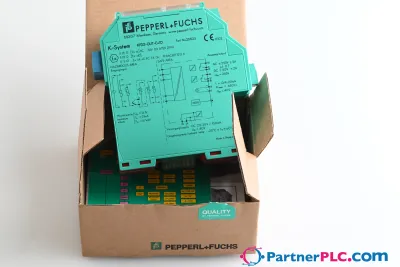 NuovoPepperl + Fuchs KFD2-GUT-EX1.D New open box
 Disponibile su richiestaPepperl Fuchs V19-W-BK15M-PUR-U-V19-G
 Disponibile su richiestaPepperl Fuchs V1SD-G-GN65M-PUR-E1S-V45-G