产品概览
| 库存情况 | 需按需确认 |
| 生命周期状态 | active |
| 保修 | 12个月(全新)· 3个月(二手/翻新) |
发货与库存
XEPIMC200 何时可以发货?
XEPIMC200 属于按需采购产品——请申请报价,我们会为这一具体单品确认准确的库存情况及发货时间。
可以亲自到店提取 XEPIMC200 吗?
可以在我们位于荷兰格罗宁根的仓库安排自提——请在下单前联系我们,确认库存情况并预约提货时间。
是否提供快递服务?
可以——在为 XEPIMC200 申请报价时告诉我们,我们会在回复中附上快递发货选项。
我们的工厂停产了,急需这个零部件——你们能帮忙吗?
如遇紧急故障,请直接致电 +31 (0)50-7110348 或发邮件至 sales@partnerplc.com 联系我们——我们可根据库存情况及目的地,为 XEPIMC200 安排当日快递或专车加急配送。
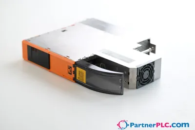
CPU I/O board, ARM Cortex A9-667, 2 GB flash memory, 512 MB DDR3L SDRAM, 32 kB FRAM, 24 VDC, 2x Ethernet interface, 1x CAN bus, 1x RS485 interface, 1x USB 2.0 interface, 1x POWERLINK interface, 1x X2X Link interface, 43 digital inputs, 24 VDC, sink/source, 2 event counters or gate time / period duration measurement, 33 digital outputs, 24 VDC, 2 A (50%), 20 digital outputs, 24 VDC, 0.5 A, 2 PWM outputs, 3 A, 8 thermocouple inputs J, K, S, N, 4 analog inputs for potentiometers, 0 to 10 V, 0 to 20 mA, 4.5 V, 14-bit, 2 analog inputs ±10 V, 14-bit, 7 analog outputs, ±10 V, 12-bit
技术规格
Specifications
| I/O module | 43 digital inputs, 6 analog inputs, 53 digital outputs, 7 analog outputs, 8 thermocouples, 2 PWM outputs |
| Interfaces | 2x Ethernet, 1x CAN bus, 1x RS485 interface, 1x POWERLINK, 1x X2X Link, 1x USB |
| B&R ID code | 0xF101 |
| Automation Studio | 4.5.01 or later |
| Automation Runtime | A4.51 or later |
| Cooling | Passive |
| Quantity | 7 |
| Status | Supply voltage OK, operating state, module status, Ethernet, CAN, RS485, POWERLINK, X2X Link |
| Power button | No |
| Reset button | Yes |
| Master capability | No |
| Buzzer | No |
| ACOPOS support | No |
| Visual Components support | No |
| Safety support | No |
| Electrical isolation | Thermocouples, Ethernet 1 (IF2), Ethernet 2 (IF3), POWERLINK (IF9) and X2X (IF10) isolated from each other and from other interfaces Power supply not isolated from channel, and channel not isolated from channel |
| CE | Yes |
| Bootloader | Automation Runtime Hardware revision ≥B0: AR 4.41 |
| CompactFlash slot | 0 |
| Real-time clock | Yes, 1 s resolution, >±10 ppm accuracy at 25°C |
| FPU | Yes |
| Type | Push/Pull |
| Clock frequency | 667 MHz |
| Data code | 24 kB |
| Program code | 32 kB |
| L2 cache | 256 kB |
| Mode/Node switches | No |
| Remanent variables | 32 kB FRAM, retention >10 years |
| Shortest task class cycle time | 1 ms |
| Typical instruction cycle time | 0.01 μs |
| RAM | 512 MB DDR3 SDRAM |
| Data retention | 10 years |
| Guaranteed | 40 TB |
| Results for 5 years | 21.9 GB/day |
| Guaranteed erase/write cycles | 20,000 |
| Error-correcting code (ECC) | Yes |
| Temperature cutoff | Yes |
| Connection designation | X6 X2X |
| Variant | 0TB1104.9000 |
| Line length | Max. 100 m between 2 nodes (segment length) |
| Max. transfer rate | 10/100 Mbit/s |
| Physical layer | 100BASE-TX |
| Half-duplex | Yes |
| Full-duplex | No |
| Autonegotiation | Yes |
| Auto-MDI/MDIX | Yes |
| Current-carrying capacity | 0.5 A |
| Transfer rate | Max. 100 Mbit/s |
| Fieldbus | POWERLINK managing or controlled node |
| Number of stations | Max. 253 |
| Internal bus power supply | No |
| Network topology | Line |
| Distance between 2 stations | Max. 100 m |
| Nominal voltage | 24 VDC |
| Input voltage | 24 VDC ±20% |
| Input current at 24 VDC | 3.2 mA |
| Additional functions | Event counter, gate and period measurement |
| Circuit | Sink or source |
| Input delay | Counter inputs 1 to 2: <4 µs Inputs 3 to 41: <1 ms |
| Low | <5 V |
| High | >15 V |
| Signal form | Square wave pulse |
| Evaluation | Positive or negative edge |
| Input frequency | Max. 100 kHz |
| Pulse length | 10 µs |
| Counter size | 16-bit |
| Supported inputs | Input 1: Counter 1 Input 2: Counter 2 |
| Internal | Yes |
| External | Max. 100 kHz |
| Length of pause between pulses | 10 µs |
| Input | Inputs 1 and 2: ±10 V Inputs 3 to 6: 0 to 10 V, 0 to 20 mA or 0 to 100% (Upot) |
| Input type | Inputs 1 and 2: Differential input Inputs 3 to 6: Single-ended input |
| Digital converter resolution | 12-bit |
| Data type | INT |
| Voltage | INT 0x8000 - 0x7FFF / 1 LSB = 0x0010 = 4.88 mV |
| Current | 0.004 %/°C |
| Current channel load | <400 Ω |
| Input protection | Protection against wiring with supply voltage |
| Gain | 0.080%, based on the current output value |
| Offset | 0.050%, based on the entire output range |
| Supply voltage UPot for potentiometer | 4.5 V / Max. 50 mA |
| Measurement range | 0.5 to 10 kΩ |
| Cutoff frequency | Inputs 1 and 2: 1 kHz Inputs 3 to 6: 10 kHz |
| Slope | 60 dB |
| Output format | INT |
| FeCuNi: Type J | -210 to 1200°C |
| NiCrNi: Type K | -270 to 1372°C |
| NiCrSi: Type N | -270 to 1300°C |
| PtRhPt: Type S | -50 to 1768°C |
| Sensor temperature | 0.1°C/LSB |
| Type J: Fe-CuNi | ±0.14% at 25°C |
| Type K: NiCr-Ni | ±0.18% at 25°C |
| Type N: NiCrSi-NiSi | ±0.16% at 25°C |
| Type S: PtRh10-Pt | ±0.34% at 25°C |
| Basic accuracy at 25°C not taking Pt1000 sensor into account | ±2°C after 10 minutes |
| Nominal output current | Screw clamp terminal blocks X12, X13 and X15: Per output: 2 A Per group: 2 A Per screw clamp terminal block: 11 A Screw clamp terminal blocks X14 and X16: Per output: 0.5 A |
| Output circuit | Sink |
| Output protection | Protection against wiring with supply voltage, short-circuit proof |
| Supply | External |
| Fuse | No internal fuse, the power supply of the outputs of each connector must be protected using a separate fuse of max. 15 A. |
| Switching frequency (resistive load) | Max. 100 Hz |
| Switching delay | Max. 500 µs |
| Supply voltage | Separately for each connector: 12 to 24 VDC ±20% |
| Supply voltage (permissible range) | External, 11 to 28 VDC |
| Nominal current | 3 A |
| Maximum load current | 3.5 A / output |
| Resistive load | ≥8 Ω |
| Inductive load | ≤10 mH |
| PWM frequency | 15 Hz to 50 kHz |
| Configurable dither | Amplitude (8-bit), frequency (2 to 500 Hz) |
| Period duration resolution | 16-bit |
| PWM mode | 15-bit + sign ≥1 µs |
| Current mode | 15-bit + sign |
| Output | ±10 V |
| Switch on/off behavior | Internal enable relay, for startup |
| 10 V | 0x7FFF |
| 0 V | 0x0000 |
| -10 V | 0x8000 |
| Max. load per output | ±10 mA (load ≥1 kΩ) |
| Max. gain drift | 0.08%, based on the current output value |
| Max. offset drift | 0.05%, based on the entire output range |
| Error caused by load change | 0.015% from 10 MΩ → 1 kΩ, resistive |
| Nonlinearity | 0.025%, based on the output range |
| Voltage range | 24 VDC ±25% |
| Power consumption | 6.5 W |
| Voltage monitoring | Yes |
| Horizontal | No |
| Vertical | Yes |
| Pollution degree per EN 60664-1 | 2 |
| Operation | 10 to 90%, non-condensing |
| Storage | 5 to 95%, non-condensing |
| Transport | 5 to 95%, non-condensing |
| Width | 190 mm |
| Height | 198 mm |
| Depth | 31 mm |
| Module dimensions including mounting plates | 190 x 198 x 31 mm (W x H x D) |