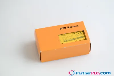
B&R X20SC0842
見積もりを依頼する



基本情報
| 在庫状況 | お問い合わせにより確認 |
| カテゴリー | Digital mixed modules |
| ライフサイクル | active |
| 保証 | 12か月(新品)・3か月(中古・整備済み) |
配送・在庫状況
X20SC0842はいつ発送できますか?
X20SC0842はお問い合わせにより調達いたします — 見積もりを依頼いただければ、この個体の正確な在庫状況と配送スケジュールをご案内いたします。
X20SC0842を直接引き取ることはできますか?
オランダ・フローニンゲンの当社倉庫での引き取りが可能な場合があります — ご注文前にお問い合わせいただき、在庫状況と引き取り日時をご確認ください。
エクスプレス配送は利用できますか?
はい — X20SC0842の見積もり依頼時にその旨をお知らせいただければ、返信にエクスプレス配送のオプションを含めてご案内いたします。
工場が停止しており緊急で必要です — 対応可能ですか?
重大な故障の場合は、+31 (0)50-7110348またはsales@partnerplc.comまで直接ご連絡ください — X20SC0842について、在庫状況と配送先に応じて即日クーリエまたは専用タクシー・ホットショット配送を検討いたします。
8 safe digital inputs, sink circuit4 pulse outputsSoftware input filter configurable for each channel4 safe digital outputs, output type A with 3 A, source circuit2 safe digital outputs, output type B with 50 mA, source circuitIntegrated output protection The module is equipped with 8 safe digital inputs and 6 safe digital outputs. It is designed for a nominal voltage of 24 VDC.The module can be used to read in digital signals and to control actuators in safety-related applications up to PL e or SIL 3.The module is equipped with filters that are individually configurable for switch-on and switch-off behavior. The module also provides pulse signals for diagnosing the sensor line.The outputs are designed using semiconductor technology so that the safety-related characteristics do not depend on the number of operating cycles. The "high-side low-side" variant (output type A) is limited to actuators without reference potential (e.g. relays, valves). Type A outputs have safety-related advantages since the actuator can be cut off in its connection cable in all error scenarios. The "high-side high-side" variant (output type B) is required for actuators with reference potential (e.g. Enable inputs on frequency inverters). It is important to observe the special notices for the cabling in this case. Safe digital output channels provide protection against automatic restart when network errors occur.This module is designed for X20 12-pin terminal blocks.
仕様
Specifications
| I/O module | 8 safe type A digital inputs, 4 pulse outputs, 24 VDC, 4 safe type A digital outputs, 24 VDC, 3 A, OSSD <500 µs, 2 safe type B2 digital outputs, 24 VDC, 50 mA, OSSD <500 µs |
| B&R ID code | 0xE7F9 |
| Status indicators | I/O function per channel, operating state, module status |
| Module run/error | Yes, using LED status indicator and software |
| Outputs | Yes, using LED status indicator and software |
| Inputs | Yes, using LED status indicator and software |
| Scope | Module |
| Function | Module functionality |
| Standalone mode | No |
| Max. I/O cycle time | 1 ms |
| Bus | 0.4 W |
| Internal I/O | 2.5 W |
| Safe digital HS-LS outputs | 0.84 |
| Safe digital HS-HS outputs | 0.175 |
| Pulse outputs | 0.8 |
| Channel - Bus | Yes |
| Channel - Channel | No |
| CE | Yes |
| UKCA | Yes |
| CRA (Cyber Resilience Act) | In preparation |
| Functional safety | EN 50156-1:2004 |
| ATEX | Zone 2, II 3G Ex nA nC IIA T5 Gc IP20, Ta (see X20 user's manual) FTZÚ 09 ATEX 0083X |
| UL | cULus E115267 Industrial control equipment |
| Note | Order 2x safety-keyed terminal block separately. Order 1x safety-keyed bus module separately. |
| Nominal voltage | 24 VDC |
| Voltage range | 24 VDC -15% / +20% |
| Integrated protective function | Reverse polarity protection |
| Quantity | 4 |
| Variant | Push-Pull |
| Input characteristics per EN 61131-2 | Type 1 |
| Hardware | ≤150 µs |
| Software | Configurable between 0 and 500 ms |
| Input circuit | Sink |
| Input voltage | 24 VDC -15% / +20% |
| Input current at 24 VDC | Min. 2 mA to max. 3.28 mA |
| Input resistance | Min. 7.33 kΩ |
| Error detection time | 1 s |
| Insulation voltage between channel and bus | 500 Veff |
| Low | <5 VDC |
| High | >15 VDC |
| Line length between signal source (pulse output or external signal) and input | Max. 60 m with unshielded line Max. 400 m with shielded line |
| Nominal output current | 50 mA |
| Total nominal current | 200 mA |
| Output protection | Shutdown of individual channels in the event of overload or short circuit |
| Braking voltage when switching off inductive loads | Max. 45 VDC |
| Error detection | 1 s |
| Peak short-circuit current | 0.5 A for 120 µs |
| Leakage current when the output is switched off | 0.1 mA |
| RDS(on) | 80 Ω |
| Switching voltage | I/O power supply minus voltage drop due to RDS(on) |
| Max. switching frequency | See section "Inrush current behavior for output channels". |
| Test pulse length | Max. 500 µs |
| Max. capacitive load | 100 nF |
| IOUT | <100 µA |
| IGND | <50 mA |
| Short-circuit current | 15 mAeff |
| Horizontal | Yes |
| Vertical | Yes |
| Installation elevation above sea level | 0 to 2000 m, no limitation |
| Degree of protection per EN 60529 | IP20 |
| Horizontal mounting orientation | 0 to 60°C |
| Vertical mounting orientation | 0 to 50°C |
| Derating | See section "Derating". |
| Storage | 5 to 95%, non-condensing |
| Transport | 5 to 95%, non-condensing |
| Operation | 5 to 95%, non-condensing |
| Pitch | 25+0.2 mm |