


Pepperl Fuchs LB2116E
Teklif İsteyin



Hızlı bilgiler
| Uygunluk | Talep üzerine onaylanır |
| Kategori | LB (Zone 2, Class I/Div. 2) |
| Yaşam döngüsü | active |
| Garanti | 12 ay (yeni) · 3 ay (kullanılmış/yenilenmiş) |
Gönderim ve uygunluk
LB2116E ne zaman gönderilebilir?
LB2116E talep üzerine temin ediliyor — bir teklif isteyin, bu spesifik ürün için tam uygunluk ve gönderim süresini onaylayalım.
LB2116E ürününü şahsen teslim alabilir miyim?
Groningen, Hollanda'daki depomuzdan şahsen teslim alma mümkün olabilir — sipariş vermeden önce uygunluğu kontrol etmek ve bir teslim alma zamanı ayarlamak için bizimle iletişime geçin.
Ekspres teslimat mevcut mu?
Evet — LB2116E için teklif isterken bunu belirtin, yanıtımızda ekspres gönderim seçeneklerini de sunalım.
Fabrikamız durdu ve buna acilen ihtiyacımız var — yardımcı olabilir misiniz?
Kritik bir arıza durumunda doğrudan +31 (0)50-7110348 numarasından veya sales@partnerplc.com adresinden bizimle iletişime geçin — uygunluk ve varış yerine bağlı olarak LB2116E için aynı gün kurye veya özel taşıma seçeneklerini değerlendirebiliriz.
Digital Output with Position Feedback. 1-channel, 1 digital output, 2 digital inputs, Mounting in Zone 2, Class I/Div.2 or in the safe area, Inputs and output Ex ia, Explosion protection: Ex ia. Occupied slots: 1. Connection: backplane bus. Rated voltage: Use only in connection with the power supplies LB9***. Power dissipation: 1.3 W. Power consumption: 1.85 W. Connection: backplane bus. Interface: manufacturer-specific bus to standard com unit. Number of channels: 2. Sensor interface: . ConnectionNAMUR sensorConnection [2]volt-free contact: . Connection: NAMUR sensor. Connection [2]: volt-free contact. Connection: channel I: 2+, 5-; channel II: 3+, 6-. Rated values: acc. to EN 60947-5-6 (NAMUR). Switching point/switching hysteresis: 1.2 ... 2.1 mA / ± 0.2 mA. Voltage: 8.2 V. Internal resistor: 1 kΩ. Line fault detection: can be switched on/off for each channel via configuration tool. Connectionmechanical switch with additional resistors (see connection diagram) proximity sensors without additional wiringShort-circuit< 360 ΩOpen-circuit< 0.35 mA: . Connection: mechanical switch with additional resistors (see connection diagram) proximity sensors without additional wiring. Short-circuit: < 360 Ω. Open-circuit: < 0.35 mA. Minimum pulse duration: 1 ms. Number of channels: 1. Suitable field devices: . Field deviceSolenoid ValveField device [2]audible alarmField device [3]visual alarm: . Field device: Solenoid Valve. Field device [2]: audible alarm. Field device [3]: visual alarm. Connection: channel I: 1+, 4-. Internal resistor: 258 Ω. Current limit: 40 mA. Open loop voltage: 23 V. Line fault detection: can be switched on/off for each channel via configuration tool , also when turned off (every 2.5 s the valve is turned on for 2 ms). Short-circuit< 50 ΩOpen-circuit> 10 kΩ: . Short-circuit: < 50 Ω. Open-circuit: > 10 kΩ. Response time: 10 ms (depending on bus cycle time). Watchdog: within 0.5 s the device goes in safe state, e.g. after loss of communication. LED indication: Power LED (P) green: supply Diagnostic LED (I) red: module fault , red flashing: communication error , white: fixed parameter set (parameters from com unit are ignored) , white flashing: requests parameters from com unit Status LED (O: output, I1: input 1, I2: input 2) red: line fault (lead breakage or short circuit) , yellow: state of digital I/O (0/1). Coding: optional mechanical coding via front socket. Electromagnetic compatibility: . Directive 2014/30/EUEN 61326-1:2013: . Directive 2014/30/EU: EN 61326-1:2013. Electromagnetic compatibility: NE 21. Degree of protection: IEC 60529. Environmental test: EN 60068-2-14. Shock resistance: EN 60068-2-27. Vibration resistance: EN 60068-2-6. Damaging gas: EN 60068-2-42. Relative humidity: EN 60068-2-78. Ambient temperature: -40 ... 60 °C (-40 ... 140 °F). Storage temperature: -40 ... 85 °C (-40 ... 185 °F). Relative humidity: 95 % non-condensing. Altitude: max. 2000 m. Shock resistance: shock type I, shock duration 11 ms, shock amplitude 15 g, number of shocks 18. Vibration resistance: frequency range 10 ... 150 Hz; transition frequency: 57.56 Hz, amplitude/acceleration ± 0.075 mm/1 g; 10 cyclesfrequency range 5 ... 100 Hz; transition frequency: 13.2 Hz amplitude/acceleration ± 1 mm/0.7 g; 90 minutes at each resonance. Damaging gas: designed for operation in environmental conditions acc. to ISA-S71.04-1985, severity level G3. Degree of protection: IP20 when mounted on backplane. Connection: removable front connector with screw flange (accessory)wiring connection via spring terminals (0.14 ... 1.5 mm2) or screw terminals (0.08 ... 1.5 mm2). Mass: approx. 150 g. Dimensions: . Height100 mmWidth16 mmDepth102 mm: . Height: 100 mm. Width: 16 mm. Depth: 102 mm. EU-type examination certificate: EXA 16 ATEX 0025X. Marking II 3(1) G Ex nA [ia Ga] IIC T4 Gc[exsign] II (1) D [Ex ia Da] IIIC [exsign] I (M1) [Ex ia Ma] I: . Marking: II 3(1) G Ex nA [ia Ga] IIC T4 Gc[exsign] II (1) D [Ex ia Da] IIIC [exsign] I (M1) [Ex ia Ma] I. Input: . VoltageUo10 VCurrentIo13 mAPowerPo33 mW (linear characteristic)Internal capacitanceCi1.2 nFInternal inductanceLi0 mH: Uo. Voltage: 10 V. Current: 13 mA. Power: 33 mW (linear characteristic). Internal capacitance: 1.2 nF. Internal inductance: 0 mH. Output: Ex ia. VoltageUo24.2 VCurrentIo108 mAPowerPo654 mWInternal capacitanceCi12 nFInternal inductanceLi0 mH: Uo. Voltage: 24.2 V. Current: 108 mA. Power: 654 mW. Internal capacitance: 12 nF. Internal inductance: 0 mH. Galvanic isolation: . Input/power supply, internal bussafe electrical isolation acc. to EN 60079-11, voltage peak value 375 VOutput/power supply, internal bussafe electrical isolation acc. to EN 60079-11, voltage peak value 375 V: . Input/power supply, internal bus: safe electrical isolation acc. to EN 60079-11, voltage peak value 375 V. Output/power supply, internal bus: safe electrical isolation acc. to EN 60079-11, voltage peak value 375 V. Directive conformity: . Directive 2014/34/EUEN IEC 60079-0:2018+AC:2020 EN 60079-11:2012 EN 60079-15:2010: . Directive 2014/34/EU: EN IEC 60079-0:2018+AC:2020 EN 60079-11:2012 EN 60079-15:2010. ATEX approval: EXA 16 ATEX 0025 X. UL approval: E106378. IECEx approval: . IECEx certificateIECEx EXA 16.0010XIECEx markingEx nA [ia Ga] IIC T4 Gc [Ex ia Da] IIIC [Ex ia Ma] I: . IECEx certificate: IECEx EXA 16.0010X. IECEx marking: Ex nA [ia Ga] IIC T4 Gc [Ex ia Da] IIIC [Ex ia Ma] I. System information: The module has to be mounted in appropriate backplanes (LB9***) in Zone 2 or outside hazardous areas. Here, observe the corresponding declaration of conformity. For use in hazardous areas (e. g. Zone 2, Zone 22 or Div. 2) the module must be installed in an appropriate enclosure.. Supplementary information: Observe the certificates, declarations of conformity, instruction manuals, and manuals where applicable. For information see www.pepperl-fuchs.com.
Teknik özellikler
Slots
| Occupied slots | 1 |
Supply
| Connection | backplane bus |
| Rated voltage | Use only in connection with the power supplies LB9*** Ur |
| Power dissipation | 1.3 W |
| Power consumption | 1.85 W |
Internal bus
| Connection | backplane bus |
| Interface | manufacturer-specific bus to standard com unit |
Digital input
| Number of channels | 2 |
| Sensor interface | |
| ConnectionNAMUR sensorConnection [2]volt-free contact | Connection |
| Connection | NAMUR sensor |
| Connection [2] | volt-free contact |
| Connection | channel I: 2+, 5-; channel II: 3+, 6- |
| Rated values | acc. to EN 60947-5-6 (NAMUR) |
| Switching point/switching hysteresis | 1.2 ... 2.1 mA / ± 0.2 mA |
| Voltage | 8.2 V |
| Internal resistor | 1 kΩ Ri |
| Line fault detection | can be switched on/off for each channel via configuration tool |
| Connectionmechanical switch with additional resistors (see connection diagram) proximity sensors without additional wiringShort-circuit< 360 ΩOpen-circuit< 0.35 mA | Connection |
| Connection | mechanical switch with additional resistors (see connection diagram) proximity sensors without additional wiring |
| Short-circuit | < 360 Ω |
| Open-circuit | < 0.35 mA |
| Minimum pulse duration | 1 ms |
Digital output
| Number of channels | 1 |
| Suitable field devices | |
| Field deviceSolenoid ValveField device [2]audible alarmField device [3]visual alarm | Field device |
| Field device | Solenoid Valve |
| Field device [2] | audible alarm |
| Field device [3] | visual alarm |
| Connection | channel I: 1+, 4- |
| Internal resistor | 258 Ω Ri |
| Current limit | 40 mA Imax |
| Open loop voltage | 23 V Us |
| Line fault detection | can be switched on/off for each channel via configuration tool , also when turned off (every 2.5 s the valve is turned on for 2 ms) |
| Short-circuit< 50 ΩOpen-circuit> 10 kΩ | Short-circuit |
| Short-circuit | < 50 Ω |
| Open-circuit | > 10 kΩ |
| Response time | 10 ms (depending on bus cycle time) |
| Watchdog | within 0.5 s the device goes in safe state, e.g. after loss of communication |
Indicators/settings
| LED indication | Power LED (P) green: supply Diagnostic LED (I) red: module fault , red flashing: communication error , white: fixed parameter set (parameters from com unit are ignored) , white flashing: requests parameters from com unit Status LED (O: output, I1: input 1, I2: input 2) red: line fault (lead breakage or short circuit) , yellow: state of digital I/O (0/1) |
| Coding | optional mechanical coding via front socket |
Directive conformity
| Electromagnetic compatibility | |
| Directive 2014/30/EUEN 61326-1:2013 | Directive 2014/30/EU |
| Directive 2014/30/EU | EN 61326-1:2013 |
Conformity
| Electromagnetic compatibility | NE 21 |
| Degree of protection | IEC 60529 |
| Environmental test | EN 60068-2-14 |
| Shock resistance | EN 60068-2-27 |
| Vibration resistance | EN 60068-2-6 |
| Damaging gas | EN 60068-2-42 |
| Relative humidity | EN 60068-2-78 |
Ambient conditions
| Ambient temperature | -40 ... 60 °C (-40 ... 140 °F) |
| Storage temperature | -40 ... 85 °C (-40 ... 185 °F) |
| Relative humidity | 95 % non-condensing |
| Altitude | max. 2000 m |
| Shock resistance | shock type I, shock duration 11 ms, shock amplitude 15 g, number of shocks 18 |
| Vibration resistance | frequency range 10 ... 150 Hz; transition frequency: 57.56 Hz, amplitude/acceleration ± 0.075 mm/1 g; 10 cyclesfrequency range 5 ... 100 Hz; transition frequency: 13.2 Hz amplitude/acceleration ± 1 mm/0.7 g; 90 minutes at each resonance |
| Damaging gas | designed for operation in environmental conditions acc. to ISA-S71.04-1985, severity level G3 |
Mechanical specifications
| Degree of protection | IP20 when mounted on backplane |
| Connection | removable front connector with screw flange (accessory)wiring connection via spring terminals (0.14 ... 1.5 mm2) or screw terminals (0.08 ... 1.5 mm2) |
| Mass | approx. 150 g |
| Dimensions | |
| Height100 mmWidth16 mmDepth102 mm | Height |
| Height | 100 mm |
| Width | 16 mm |
| Depth | 102 mm |
Data for application in connection with hazardous areas
| EU-type examination certificate | EXA 16 ATEX 0025X |
| Marking II 3(1) G Ex nA [ia Ga] IIC T4 Gc[exsign] II (1) D [Ex ia Da] IIIC [exsign] I (M1) [Ex ia Ma] I | Marking |
| Marking | II 3(1) G Ex nA [ia Ga] IIC T4 Gc[exsign] II (1) D [Ex ia Da] IIIC [exsign] I (M1) [Ex ia Ma] I |
| Input | |
| VoltageUo10 VCurrentIo13 mAPowerPo33 mW (linear characteristic)Internal capacitanceCi1.2 nFInternal inductanceLi0 mH | Uo Voltage |
| Voltage | 10 V Uo |
| Current | 13 mA Io |
| Power | 33 mW (linear characteristic) Po |
| Internal capacitance | 1.2 nF Ci |
| Internal inductance | 0 mH Li |
| Output | Ex ia |
| VoltageUo24.2 VCurrentIo108 mAPowerPo654 mWInternal capacitanceCi12 nFInternal inductanceLi0 mH | Uo Voltage |
| Voltage | 24.2 V Uo |
| Current | 108 mA Io |
| Power | 654 mW Po |
| Internal capacitance | 12 nF Ci |
| Internal inductance | 0 mH Li |
| Galvanic isolation | |
| Input/power supply, internal bussafe electrical isolation acc. to EN 60079-11, voltage peak value 375 VOutput/power supply, internal bussafe electrical isolation acc. to EN 60079-11, voltage peak value 375 V | Input/power supply, internal bus |
| Input/power supply, internal bus | safe electrical isolation acc. to EN 60079-11, voltage peak value 375 V |
| Output/power supply, internal bus | safe electrical isolation acc. to EN 60079-11, voltage peak value 375 V |
| Directive conformity | |
| Directive 2014/34/EUEN IEC 60079-0:2018+AC:2020 EN 60079-11:2012 EN 60079-15:2010 | Directive 2014/34/EU |
| Directive 2014/34/EU | EN IEC 60079-0:2018+AC:2020 EN 60079-11:2012 EN 60079-15:2010 |
International approvals
| ATEX approval | EXA 16 ATEX 0025 X |
| UL approval | E106378 |
| IECEx approval | |
| IECEx certificateIECEx EXA 16.0010XIECEx markingEx nA [ia Ga] IIC T4 Gc [Ex ia Da] IIIC [Ex ia Ma] I | IECEx certificate |
| IECEx certificate | IECEx EXA 16.0010X |
| IECEx marking | Ex nA [ia Ga] IIC T4 Gc [Ex ia Da] IIIC [Ex ia Ma] I |
General information
| System information | The module has to be mounted in appropriate backplanes (LB9***) in Zone 2 or outside hazardous areas. Here, observe the corresponding declaration of conformity. For use in hazardous areas (e. g. Zone 2, Zone 22 or Div. 2) the module must be installed in an appropriate enclosure. |
| Supplementary information | Observe the certificates, declarations of conformity, instruction manuals, and manuals where applicable. For information see www.pepperl-fuchs.com. |
Daha fazla Pepperl Fuchs parçası
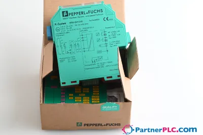 YeniPepperl + Fuchs KFD2-GUT-EX1.D New open box
 Talep üzerine temin edilirPepperl Fuchs V19-W-BK15M-PUR-U-V19-G
 Talep üzerine temin edilirPepperl Fuchs V1SD-G-GN65M-PUR-E1S-V45-G