
Pepperl Fuchs PS1000-D2-24.20.RM
Poproś o wycenę



Najważniejsze informacje
| Dostępność | Potwierdzenie na zapytanie |
| Kategoria | Industrial Power Supplies |
| Cykl życia | active |
| Gwarancja | 12 miesięcy (nowe) · 3 miesiące (używane/odnowione) |
Wysyłka i dostępność
Kiedy PS1000-D2-24.20.RM może zostać wysłany?
PS1000-D2-24.20.RM jest sprowadzany na zamówienie — poproś o wycenę, a potwierdzimy dokładną dostępność i czas realizacji dla tej konkretnej sztuki.
Czy mogę odebrać PS1000-D2-24.20.RM osobiście?
Odbiór osobisty w naszym magazynie w Groningen w Holandii może być możliwy — skontaktuj się z nami przed złożeniem zamówienia, aby potwierdzić dostępność i ustalić termin odbioru.
Czy dostępna jest dostawa ekspresowa?
Tak — wspomnij o tym w zapytaniu ofertowym dotyczącym PS1000-D2-24.20.RM, a w odpowiedzi podamy opcje dostawy ekspresowej.
Nasz zakład stoi i pilnie tego potrzebujemy — czy możecie pomóc?
W przypadku krytycznej awarii skontaktuj się z nami bezpośrednio pod numerem +31 (0)50-7110348 lub e-mailem sales@partnerplc.com — sprawdzimy możliwość kuriera tego samego dnia lub dedykowanego transportu dla PS1000-D2-24.20.RM, w zależności od dostępności i miejsca docelowego.
Redundancy Module. 24 V DC to 28 V DC input, 2 inputs with 1 output, Output 24 V DC, 20 A, Housing width 32 mm, Built-in decoupling mosfets for 1+1 and N+1 redundancy, Automatic load sharing, Reverse input polarity protection, Easy wiring: distribution terminal for negative pole included, Redundancy status indicator, Suitable for Zone 2/Div. 2 mounting, Device type: device for DIN rail mounting, Function: Redundancy Module, Voltage range: 24 ... 28 V DC. Voltage drop: input to output 0.1 ... 0.5 V at input 2 x 5 A 0.2 ... 0.5 V at input 2 x 10 A 0.24 ... 0.5 V at input 2 x 12 A load share dependent. Power dissipation: 1.7 W no load 2.6 ... 4.7 W at input 2 x 5 A 5.6 ... 8.7 W at input 2 x 10 A. Rated voltage: 24 ... 28 V. Voltage range: 18 ... 35 V DC. Current: 2 x 12 A at ambient temperature < 45 °C (113 °F) 2 x 10 A at ambient temperature 70 °C (158 °F) 2x 17 mA for max. 5 s for lower output currents see technical information. Voltage range: 24 ... 28 V DC. Current: 24 A at ambient temperature < 45 °C (113 °F) 20 A at ambient temperature < 70 °C (158 °F) 32.5 A for max. 5 s max. 26 A in overload or short circuit mode (voltage < 6 V DC). Connection: terminals 13, 14 : relay contact load share terminals 23, 24 : relay contact redundancy. Output type: relay contact load share - contact is closed if the adjustment of the output voltages are sufficient - contact is open if an even load share does not occur and readjustment of the output voltage is required relay contact redundancy - contact is closed if no fault is detected - contact is open if one or both input voltages are below 22 V DC or above 30 V DC- contact is open if the output current is higher than the adjusted value of the output current- contact is open if an internal defect of the device is detected. Contact loading: max. 60 V DC/0.3 A ; 30 V DC/1 A ; 30 V AC/0.5 A resistive load min. 1 mA at 5 V DC. Input/Output: SELV/PELV. Display elements: LED green: output status- LED lights up if the output current is smaller than the adjusted value of the output current LEDs green: load share status- LEDs indicate the load share status between the two power supplies LED green: redundancy status- LED lights up if no fault is detected- LED flashes if one ore both input values are below 22 V or above 30 V- LED flashes if the output current is higher than the adjusted value of the output current- LED flashes if an internal defect is detected. Control elements: rotary switch. Configuration: setting of the output current via rotary switch - switch setting to 5 A in combination with two 5A power supplies (1+1 redundancy)- switch setting to 10 A in combination with two 10A power supplies (1+1 redundancy)- switch setting to 20 A for N+1 redundant systems. Electromagnetic compatibility: . Directive 2014/30/EUIEC/EN 61000-6-1 , IEC/EN 61000-6-2 , IEC/EN 61000-6-3 , IEC/EN 61000-6-4: . Directive 2014/30/EU: IEC/EN 61000-6-1 , IEC/EN 61000-6-2 , IEC/EN 61000-6-3 , IEC/EN 61000-6-4. Low voltage: . Directive 2014/35/EUEN 61010-1: . Directive 2014/35/EU: EN 61010-1. RoHS: . Directive 2011/65/EU (RoHS)IEC/EN 63000:2019: . Directive 2011/65/EU (RoHS): IEC/EN 63000:2019. Degree of protection: EN 60529. Shock resistance: EN 60068-2-27. Vibration resistance: EN 60068-2-6. Ambient temperature: -40 ... 70 °C (-40 ... 158 °F) , see technical information. Storage temperature: -40 ... 85 °C (-40 ... 185 °F). Relative humidity: 5 ... 95 %, noncondensing. Shock resistance: 20 g , 11 ms or 30 g , 6 ms. Vibration resistance: 2 ... 17.8 Hz : ± 1.6 mm , 17.8 ... 500 Hz : 2 g. Housing material: aluminum alloy , galvanized steel. Degree of protection: IP20. Connection: . Input/Outputscrew terminals conductor cross section: max. 6 mm2 (AWG 20-10) cable diameter: max. 2.8 mm, wire end ferrules included stripped insulation length: 7 mm tightening torque: max. 0.8 NmRelay contact outputspring terminals conductor cross section: max. 1.5 mm2 (AWG 24-16) cable diameter: max. 1.6 mm, wire end ferrules included stripped insulation length: 7 mm: . Input/Output: screw terminals conductor cross section: max. 6 mm2 (AWG 20-10) cable diameter: max. 2.8 mm, wire end ferrules included stripped insulation length: 7 mm tightening torque: max. 0.8 Nm. Relay contact output: spring terminals conductor cross section: max. 1.5 mm2 (AWG 24-16) cable diameter: max. 1.6 mm, wire end ferrules included stripped insulation length: 7 mm. Mass: approx. 310 g. Dimensions: 32 x 124 x 117 mm (W x H x D) , without DIN mounting rail. Height124 mmWidth32 mmDepth117 mm: . Height: 124 mm. Width: 32 mm. Depth: 117 mm. Mounting: on 35 mm DIN mounting rail acc. to EN 60715:2001. ATEX approval: . ATEX certificateEPS 11 ATEX 1 312 XATEX marking II 3G Ex ec nC II T4 Gc: . ATEX certificate: EPS 11 ATEX 1 312 X. ATEX marking: II 3G Ex ec nC II T4 Gc. Directive conformity: . Directive 2014/34/EUEN 60079-0:2012+A11:2013 , EN 60079-7:2016 , EN 60079-15:2010: . Directive 2014/34/EU: EN 60079-0:2012+A11:2013 , EN 60079-7:2016 , EN 60079-15:2010. UL approval: E223176. IECEx approval: . IECEx certificateIECEx EPS 20.0057XIECEx markingEx ec nC IIC T4 GcStandardsIEC 60079-0:2011 , IEC 60079-7:2015 , IEC 60079-15:2010: . IECEx certificate: IECEx EPS 20.0057X. IECEx marking: Ex ec nC IIC T4 Gc. Standards: IEC 60079-0:2011 , IEC 60079-7:2015 , IEC 60079-15:2010. Supplementary information: Observe the certificates, declarations of conformity, instruction manuals, and manuals where applicable. For information see www.pepperl-fuchs.com.
Specyfikacja
Electrical specifications
| Voltage drop | input to output 0.1 ... 0.5 V at input 2 x 5 A 0.2 ... 0.5 V at input 2 x 10 A 0.24 ... 0.5 V at input 2 x 12 A load share dependent |
| Power dissipation | 1.7 W no load 2.6 ... 4.7 W at input 2 x 5 A 5.6 ... 8.7 W at input 2 x 10 A |
Input
| Rated voltage | 24 ... 28 V Ur |
| Voltage range | 18 ... 35 V DC |
| Current | 2 x 12 A at ambient temperature < 45 °C (113 °F) 2 x 10 A at ambient temperature 70 °C (158 °F) 2x 17 mA for max. 5 s for lower output currents see technical information |
Output
| Voltage range | 24 ... 28 V DC |
| Current | 24 A at ambient temperature < 45 °C (113 °F) 20 A at ambient temperature < 70 °C (158 °F) 32.5 A for max. 5 s max. 26 A in overload or short circuit mode (voltage < 6 V DC) |
Fault indication output
| Connection | terminals 13, 14 : relay contact load share terminals 23, 24 : relay contact redundancy |
| Output type | relay contact load share - contact is closed if the adjustment of the output voltages are sufficient - contact is open if an even load share does not occur and readjustment of the output voltage is required relay contact redundancy - contact is closed if no fault is detected - contact is open if one or both input voltages are below 22 V DC or above 30 V DC- contact is open if the output current is higher than the adjusted value of the output current- contact is open if an internal defect of the device is detected |
| Contact loading | max. 60 V DC/0.3 A ; 30 V DC/1 A ; 30 V AC/0.5 A resistive load min. 1 mA at 5 V DC |
Galvanic isolation
| Input/Output | SELV/PELV |
Indicators/settings
| Display elements | LED green: output status- LED lights up if the output current is smaller than the adjusted value of the output current LEDs green: load share status- LEDs indicate the load share status between the two power supplies LED green: redundancy status- LED lights up if no fault is detected- LED flashes if one ore both input values are below 22 V or above 30 V- LED flashes if the output current is higher than the adjusted value of the output current- LED flashes if an internal defect is detected |
| Control elements | rotary switch |
| Configuration | setting of the output current via rotary switch - switch setting to 5 A in combination with two 5A power supplies (1+1 redundancy)- switch setting to 10 A in combination with two 10A power supplies (1+1 redundancy)- switch setting to 20 A for N+1 redundant systems |
Directive conformity
| Electromagnetic compatibility | |
| Directive 2014/30/EUIEC/EN 61000-6-1 , IEC/EN 61000-6-2 , IEC/EN 61000-6-3 , IEC/EN 61000-6-4 | Directive 2014/30/EU |
| Directive 2014/30/EU | IEC/EN 61000-6-1 , IEC/EN 61000-6-2 , IEC/EN 61000-6-3 , IEC/EN 61000-6-4 |
| Low voltage | |
| Directive 2014/35/EUEN 61010-1 | Directive 2014/35/EU |
| Directive 2014/35/EU | EN 61010-1 |
| RoHS | |
| Directive 2011/65/EU (RoHS)IEC/EN 63000:2019 | Directive 2011/65/EU (RoHS) |
| Directive 2011/65/EU (RoHS) | IEC/EN 63000:2019 |
Conformity
| Degree of protection | EN 60529 |
| Shock resistance | EN 60068-2-27 |
| Vibration resistance | EN 60068-2-6 |
Ambient conditions
| Ambient temperature | -40 ... 70 °C (-40 ... 158 °F) , see technical information |
| Storage temperature | -40 ... 85 °C (-40 ... 185 °F) |
| Relative humidity | 5 ... 95 %, noncondensing |
| Shock resistance | 20 g , 11 ms or 30 g , 6 ms |
| Vibration resistance | 2 ... 17.8 Hz : ± 1.6 mm , 17.8 ... 500 Hz : 2 g |
Mechanical specifications
| Housing material | aluminum alloy , galvanized steel |
| Degree of protection | IP20 |
| Connection | |
| Input/Outputscrew terminals conductor cross section: max. 6 mm2 (AWG 20-10) cable diameter: max. 2.8 mm, wire end ferrules included stripped insulation length: 7 mm tightening torque: max. 0.8 NmRelay contact outputspring terminals conductor cross section: max. 1.5 mm2 (AWG 24-16) cable diameter: max. 1.6 mm, wire end ferrules included stripped insulation length: 7 mm | Input/Output |
| Input/Output | screw terminals conductor cross section: max. 6 mm2 (AWG 20-10) cable diameter: max. 2.8 mm, wire end ferrules included stripped insulation length: 7 mm tightening torque: max. 0.8 Nm |
| Relay contact output | spring terminals conductor cross section: max. 1.5 mm2 (AWG 24-16) cable diameter: max. 1.6 mm, wire end ferrules included stripped insulation length: 7 mm |
| Mass | approx. 310 g |
| Dimensions | 32 x 124 x 117 mm (W x H x D) , without DIN mounting rail |
| Height124 mmWidth32 mmDepth117 mm | Height |
| Height | 124 mm |
| Width | 32 mm |
| Depth | 117 mm |
| Mounting | on 35 mm DIN mounting rail acc. to EN 60715:2001 |
Data for application in connection with hazardous areas
| ATEX approval | |
| ATEX certificateEPS 11 ATEX 1 312 XATEX marking II 3G Ex ec nC II T4 Gc | ATEX certificate |
| ATEX certificate | EPS 11 ATEX 1 312 X |
| ATEX marking | II 3G Ex ec nC II T4 Gc |
| Directive conformity | |
| Directive 2014/34/EUEN 60079-0:2012+A11:2013 , EN 60079-7:2016 , EN 60079-15:2010 | Directive 2014/34/EU |
| Directive 2014/34/EU | EN 60079-0:2012+A11:2013 , EN 60079-7:2016 , EN 60079-15:2010 |
International approvals
| UL approval | E223176 |
| IECEx approval | |
| IECEx certificateIECEx EPS 20.0057XIECEx markingEx ec nC IIC T4 GcStandardsIEC 60079-0:2011 , IEC 60079-7:2015 , IEC 60079-15:2010 | IECEx certificate |
| IECEx certificate | IECEx EPS 20.0057X |
| IECEx marking | Ex ec nC IIC T4 Gc |
| Standards | IEC 60079-0:2011 , IEC 60079-7:2015 , IEC 60079-15:2010 |
General information
| Supplementary information | Observe the certificates, declarations of conformity, instruction manuals, and manuals where applicable. For information see www.pepperl-fuchs.com. |
Więcej części Pepperl Fuchs
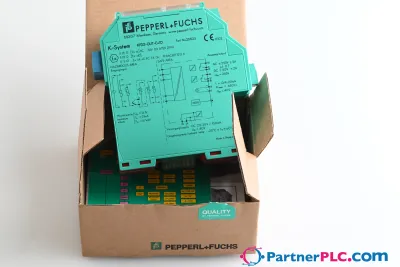 NowyPepperl + Fuchs KFD2-GUT-EX1.D New open box
 Dostępny na zapytaniePepperl Fuchs V19-W-BK15M-PUR-U-V19-G
 Dostępny na zapytaniePepperl Fuchs V1SD-G-GN65M-PUR-E1S-V45-G