


Pepperl Fuchs HiC2877
Richiedi un preventivo



In breve
| Disponibilità | Conferma su richiesta |
| Categoria | H-System (Termination Board Mounting) |
| Ciclo di vita | active |
| Garanzia | 12 mesi (nuovo) · 3 mesi (usato/rigenerato) |
Spedizione e disponibilità
Quando può essere spedito HiC2877?
HiC2877 viene reperito su richiesta — richiedi un preventivo e ti confermeremo disponibilità e tempi di consegna esatti per questa unità specifica.
Posso ritirare HiC2877 di persona?
Il ritiro presso il nostro magazzino di Groningen, Paesi Bassi, potrebbe essere possibile — contattaci prima dell'ordine per verificare disponibilità e concordare un orario di ritiro.
È disponibile la consegna espressa?
Sì — menzionalo nella richiesta di preventivo per HiC2877 e includeremo le opzioni di spedizione espressa nella nostra risposta.
Il nostro impianto è fermo e ci serve con urgenza: potete aiutarci?
In caso di guasto critico, contattaci direttamente al +31 (0)50-7110348 o a sales@partnerplc.com — valuteremo un corriere in giornata o una consegna dedicata per HiC2877, in base a disponibilità e destinazione.
Solenoid Driver. 1-channel isolated barrier, 24 V DC supply (bus or loop powered), Output 40 mA at 11.2 V DC, 55 mA current limit, Contact or logic control input, Entity parameter I<sub>o</sub>/I<sub>sc</sub> = 93 mA, Line fault detection (LFD), Test pulse immunity, Up to SIL 3 acc. to IEC/EN 61508 (loop powered), Housing width: 12.5 mm, Number of channels: 1-channel, Filter, Safety Integrity Level (SIL): SIL 3, Systematic capability (SC): SC 3. Signal type: Digital Output. Safety Integrity Level (SIL): SIL 3. Systematic capability (SC): SC 3. Connection: SL1: 1a, 1b(-); 2a, 2b(+). Rated voltage: 20.4 ... 30 V DC loop powered 20.4 ... 30 V DC bus powered via Termination Board. Input current: 62 mA at 24 V, 300 Ω load. Power dissipation: 1 W at 24 V, 300 Ω load. Connection side: control side. Connection: SL1: 8a(+), 7a(-) loop powered SL1: 10a(+), 9a(-) bus powered. Control input: external switch (dry contact or open collector) non isolated or logic signal input fully floating. Signal level: 1-signal: 15...30 V DC (current limited to 3 mA) or contact close (internal 10 kΩ pull-up)0-signal: 0...5 V DC or contact open. Power dissipation: 1 W at 24 V, 300 Ω load for loop powered. Inrush current: 0.2 A , 15 ms loop powered. Connection side: field side. Connection: SL2: 5a(+), 5b(-). Internal resistor: approx. 280 Ω. Current: ≤ 40 mA. Voltage: ≥ 11.2 V. Current limit: 55 mA. Open loop voltage: approx. 22.5 V. Load: nominal 0.1 ... 5 kΩ. Switching frequency: - bus powered: filter OFF: max. 150 Hz, filter ON: max. 15 Hz- loop powered: max. 10 Hz. Energized/De-energized delay: - bus powered: filter OFF: 1 ms, filter ON: 10 ms- loop powered: switch-on 50 ms, switch-off 6 ms (300 Ω load). Line fault detection: . Short-circuit< 25 ΩOpen-circuit> 100 kΩTest current< 4 mA: . Short-circuit: < 25 Ω. Open-circuit: > 100 kΩ. Test current: < 4 mA. Connection: SL1: 6b. Output type: open collector transistor (internal fault bus). Fault current: 4 mA pulsing (20 ms ON, 200 ms OFF). Fault level: lead short-circuit detection at < 25 Ωlead breakage detection at > 100 kΩ typical. Output/power supply, inputs, and collective error: safe electrical isolation acc. to EN 60079-11: 2007, voltage peak value 375 V. Display elements: LEDs. Control elements: DIP switch. Factory setting: bus powered, input: dry contact, line fault detection enabled. Configuration: via DIP switches. Labeling: space for labeling at the front. Electromagnetic compatibility: . Directive 2014/30/EUEN 61326-1:2013 (industrial locations): . Directive 2014/30/EU: EN 61326-1:2013 (industrial locations). Electromagnetic compatibility: NE 21:2006For further information see system description.. Degree of protection: IEC 60529:2001. Ambient temperature: -20 ... 60 °C (-4 ... 140 °F). Degree of protection: IP20. Mass: approx. 100 g. Dimensions: 12.5 x 106 x 128 mm (0.5 x 4.2 x 5.1 inch) (W x H x D). Height106 mmWidth12.5 mmDepth128 mm: . Height: 106 mm. Width: 12.5 mm. Depth: 128 mm. Mounting: on termination board. Coding: pin 2 and 3 trimmed For further information see system description.. EU-type examination certificate: CESI 10 ATEX 046. Marking II (1)G [Ex ia Ga] IIC [exsign] II (1)D [Ex ia Da] IIIC [exsign] I (M1) [Ex ia Ma] IOutputEx ia Ga, Ex ia Da, Ex ia MaVoltageUo25.2 VCurrentIo93 mAPowerPo586 mW: . Marking: II (1)G [Ex ia Ga] IIC [exsign] II (1)D [Ex ia Da] IIIC [exsign] I (M1) [Ex ia Ma] I. Output: Ex ia Ga, Ex ia Da, Ex ia Ma. Voltage: 25.2 V. Current: 93 mA. Power: 586 mW. Supply: . Maximum safe voltageUm253 V AC (Attention! Um is no rated voltage.): Um. Maximum safe voltage: 253 V AC (Attention! Um is no rated voltage.). Certificate: KIWA 15 ATEX 0036 X. Marking II 3G Ex ec IIC T4 Gc: . Marking: II 3G Ex ec IIC T4 Gc. Directive conformity: . Directive 2014/34/EUEN 60079-0:2012+A11:2013 , EN 60079-11:2012 , EN 60079-7:2015+A1:2018: . Directive 2014/34/EU: EN 60079-0:2012+A11:2013 , EN 60079-11:2012 , EN 60079-7:2015+A1:2018. FM approval: . Control drawing116-0431 (cFMus): . Control drawing: 116-0431 (cFMus). UL approval: . Control drawing116-0383 (cULus): . Control drawing: 116-0383 (cULus). IECEx approval: . IECEx certificateIECEx CES 10.0017 IECEx KIWA 15.0018XIECEx marking[Ex ia Ga] IIC, [Ex ia Da] IIIC, [Ex ia Ma] I Ex ec IIC T4 Gc: . IECEx certificate: IECEx CES 10.0017 IECEx KIWA 15.0018X. IECEx marking: [Ex ia Ga] IIC, [Ex ia Da] IIIC, [Ex ia Ma] I Ex ec IIC T4 Gc. Supplementary information: Observe the certificates, declarations of conformity, instruction manuals, and manuals where applicable. For information see www.pepperl-fuchs.com.
Specifiche
General specifications
| Signal type | Digital Output |
Functional safety related parameters
| Safety Integrity Level (SIL) | SIL 3 |
| Systematic capability (SC) | SC 3 |
Supply
| Connection | SL1: 1a, 1b(-); 2a, 2b(+) |
| Rated voltage | 20.4 ... 30 V DC loop powered 20.4 ... 30 V DC bus powered via Termination Board Ur |
| Input current | 62 mA at 24 V, 300 Ω load |
| Power dissipation | 1 W at 24 V, 300 Ω load |
Input
| Connection side | control side |
| Connection | SL1: 8a(+), 7a(-) loop powered SL1: 10a(+), 9a(-) bus powered |
| Control input | external switch (dry contact or open collector) non isolated or logic signal input fully floating |
| Signal level | 1-signal: 15...30 V DC (current limited to 3 mA) or contact close (internal 10 kΩ pull-up)0-signal: 0...5 V DC or contact open |
| Power dissipation | 1 W at 24 V, 300 Ω load for loop powered |
| Inrush current | 0.2 A , 15 ms loop powered |
Output
| Connection side | field side |
| Connection | SL2: 5a(+), 5b(-) |
| Internal resistor | approx. 280 Ω Ri |
| Current | ≤ 40 mA Ie |
| Voltage | ≥ 11.2 V Ue |
| Current limit | 55 mA Imax |
| Open loop voltage | approx. 22.5 V Us |
| Load | nominal 0.1 ... 5 kΩ |
| Switching frequency | - bus powered: filter OFF: max. 150 Hz, filter ON: max. 15 Hz- loop powered: max. 10 Hz f |
| Energized/De-energized delay | - bus powered: filter OFF: 1 ms, filter ON: 10 ms- loop powered: switch-on 50 ms, switch-off 6 ms (300 Ω load) |
| Line fault detection | |
| Short-circuit< 25 ΩOpen-circuit> 100 kΩTest current< 4 mA | Short-circuit |
| Short-circuit | < 25 Ω |
| Open-circuit | > 100 kΩ |
| Test current | < 4 mA |
Fault indication output
| Connection | SL1: 6b |
| Output type | open collector transistor (internal fault bus) |
| Fault current | 4 mA pulsing (20 ms ON, 200 ms OFF) |
| Fault level | lead short-circuit detection at < 25 Ωlead breakage detection at > 100 kΩ typical |
Galvanic isolation
| Output/power supply, inputs, and collective error | safe electrical isolation acc. to EN 60079-11: 2007, voltage peak value 375 V |
Indicators/settings
| Display elements | LEDs |
| Control elements | DIP switch |
| Factory setting | bus powered, input: dry contact, line fault detection enabled |
| Configuration | via DIP switches |
| Labeling | space for labeling at the front |
Directive conformity
| Electromagnetic compatibility | |
| Directive 2014/30/EUEN 61326-1:2013 (industrial locations) | Directive 2014/30/EU |
| Directive 2014/30/EU | EN 61326-1:2013 (industrial locations) |
Conformity
| Electromagnetic compatibility | NE 21:2006For further information see system description. |
| Degree of protection | IEC 60529:2001 |
Ambient conditions
| Ambient temperature | -20 ... 60 °C (-4 ... 140 °F) |
Mechanical specifications
| Degree of protection | IP20 |
| Mass | approx. 100 g |
| Dimensions | 12.5 x 106 x 128 mm (0.5 x 4.2 x 5.1 inch) (W x H x D) |
| Height106 mmWidth12.5 mmDepth128 mm | Height |
| Height | 106 mm |
| Width | 12.5 mm |
| Depth | 128 mm |
| Mounting | on termination board |
| Coding | pin 2 and 3 trimmed For further information see system description. |
Data for application in connection with hazardous areas
| EU-type examination certificate | CESI 10 ATEX 046 |
| Marking II (1)G [Ex ia Ga] IIC [exsign] II (1)D [Ex ia Da] IIIC [exsign] I (M1) [Ex ia Ma] IOutputEx ia Ga, Ex ia Da, Ex ia MaVoltageUo25.2 VCurrentIo93 mAPowerPo586 mW | Marking |
| Marking | II (1)G [Ex ia Ga] IIC [exsign] II (1)D [Ex ia Da] IIIC [exsign] I (M1) [Ex ia Ma] I |
| Output | Ex ia Ga, Ex ia Da, Ex ia Ma |
| Voltage | 25.2 V Uo |
| Current | 93 mA Io |
| Power | 586 mW Po |
| Supply | |
| Maximum safe voltageUm253 V AC (Attention! Um is no rated voltage.) | Um Maximum safe voltage |
| Maximum safe voltage | 253 V AC (Attention! Um is no rated voltage.) Um |
| Certificate | KIWA 15 ATEX 0036 X |
| Marking II 3G Ex ec IIC T4 Gc | Marking |
| Marking | II 3G Ex ec IIC T4 Gc |
| Directive conformity | |
| Directive 2014/34/EUEN 60079-0:2012+A11:2013 , EN 60079-11:2012 , EN 60079-7:2015+A1:2018 | Directive 2014/34/EU |
| Directive 2014/34/EU | EN 60079-0:2012+A11:2013 , EN 60079-11:2012 , EN 60079-7:2015+A1:2018 |
International approvals
| FM approval | |
| Control drawing116-0431 (cFMus) | Control drawing |
| Control drawing | 116-0431 (cFMus) |
| UL approval | |
| Control drawing116-0383 (cULus) | Control drawing |
| Control drawing | 116-0383 (cULus) |
| IECEx approval | |
| IECEx certificateIECEx CES 10.0017 IECEx KIWA 15.0018XIECEx marking[Ex ia Ga] IIC, [Ex ia Da] IIIC, [Ex ia Ma] I Ex ec IIC T4 Gc | IECEx certificate |
| IECEx certificate | IECEx CES 10.0017 IECEx KIWA 15.0018X |
| IECEx marking | [Ex ia Ga] IIC, [Ex ia Da] IIIC, [Ex ia Ma] I Ex ec IIC T4 Gc |
General information
| Supplementary information | Observe the certificates, declarations of conformity, instruction manuals, and manuals where applicable. For information see www.pepperl-fuchs.com. |
Altri componenti Pepperl Fuchs
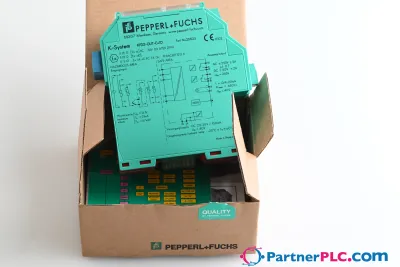 NuovoPepperl + Fuchs KFD2-GUT-EX1.D New open box
 Disponibile su richiestaPepperl Fuchs V19-W-BK15M-PUR-U-V19-G
 Disponibile su richiestaPepperl Fuchs V1SD-G-GN65M-PUR-E1S-V45-G