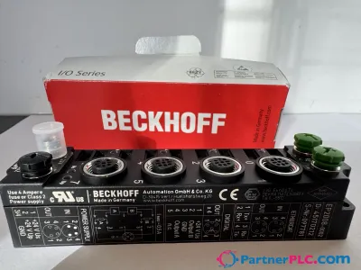
Fieldbus Box, 4-channel analog output, DeviceNet®, current, 0/4…20 mA, 16 bit, single-ended, M12
Demander un devis



En bref
| Disponibilité | Confirmation sur demande |
| Catégorie | IP4112-Bxxx |
| Cycle de vie | active |
| Garantie | 12 mois (neuf) · 3 mois (occasion/reconditionné) |
Livraison & disponibilité
Quand IP4112-B520 peut-il être expédié ?
IP4112-B520 est approvisionné sur demande — demandez un devis et nous confirmerons la disponibilité exacte et le délai de livraison pour cette pièce précise.
Puis-je récupérer IP4112-B520 en personne ?
Un retrait dans notre entrepôt de Groningue, Pays-Bas, est parfois possible — contactez-nous avant de commander pour vérifier la disponibilité et convenir d'un horaire de retrait.
La livraison express est-elle disponible ?
Oui — mentionnez-le lors de votre demande de devis pour IP4112-B520 et nous inclurons les options de livraison express dans notre réponse.
Notre usine est à l'arrêt et nous en avons besoin de toute urgence — pouvez-vous aider ?
En cas de panne critique, contactez-nous directement au +31 (0)50-7110348 ou à sales@partnerplc.com — nous étudierons une livraison le jour même par coursier ou taxi dédié pour IP4112-B520, selon la disponibilité et la destination.
The IP4112 analog output module generates analog output signals in the range from 0/4 to 20 mA. The power is supplied to the process level with a resolution of 15 bits (default), and is electrically isolated. If the input is transmitted without an
Caractéristiques
Specifications
| Number of channels | 4 analog outputs |
| Number of outputs | 4 |
| Output connections | M12, screw type |
| Signal current | 0/4…20 mA |
| Nominal voltage | 24 V DC |
| Load | 500 Ω |
| Resolution | 15 bit, configurable to 16 bit |
| Conversion time | 4 ms |
| Measurement error/uncertainty | ±0.1% (relative to full scale value) |
| Actuator supply | from the auxiliary voltage UP |
| Power supply connection | feed: 1 x M8 male socket, 4-pin, a-coded; downstream connection: 1 x M8 female socket, 4-pin, a-coded |
| Bit width in the process image | output: 4 x 16 bit data, optional: 4 x 8 bit control/status |
| Electrical isolation | control voltage/fieldbus: 500 V, control voltage/inputs or outputs: according to I/O type |
| Current consumption from US (without sensor current) | see documentation |
| Extension modules | – |
| Digital peripheral signals | according to I/O type |
| Analog peripheral signals | according to I/O type |
| Configuration | via KS2000 or the controller (explicit messaging) |
| Data transfer rates | automatic detection up to 500 kbaud |
| Bus interface | 1 x M12 plug, 5-pin |
| Data transfer medium | shielded copper cable, with power supply, typ. 2 x 2 x 0.25 mm² |
| Power supply | control voltage: 24 V DC (-15%/+20%); load voltage: according to I/O type |
| Box supply current | 45 mA + current consumption of sensors, max. 0.5 A |
| Auxiliary power current | according to I/O type |
| Distance between stations | 500 m 250 m 100 m |
| Operating modes | bit strobe, polling, cyclic, change of state (COS) |
| Operating temperature | 0…55°C |
| Storage temperature | -25…+85°C |
| Vibration/shock resistance | conforms to EN 60068-2-6/EN 60068-2-27 |
| EMC immunity/emission | conforms to EN 61000-6-2/EN 61000-6-4 |
| Protect. rating/installation pos. | IP65/66/67 (conforms to EN 60529)/variable |
| Approvals/markings | CE, UL |
| Dimensions (W x H x D) | 30 mm x 175 mm x 26.5 mm |
| Material | PA6 (polyamide) |
| Installation | 2 fixing holes 3.5 mm diameter for M3 |