
B&R X20CM1201
Solicitar presupuesto



Datos rápidos
| Disponibilidad | Confirmación bajo consulta |
| Categoría | Digital signal processing and preparation |
| Ciclo de vida | active |
| Garantía | 12 meses (nuevo) · 3 meses (usado/reacondicionado) |
Envío y disponibilidad
¿Cuándo se puede enviar X20CM1201?
X20CM1201 se abastece bajo pedido — solicite un presupuesto y confirmaremos la disponibilidad exacta y el plazo de entrega para esta unidad concreta.
¿Puedo recoger X20CM1201 en persona?
Es posible recoger el pedido en nuestro almacén de Groningen, Países Bajos — contáctenos antes de realizar el pedido para confirmar disponibilidad y acordar un horario de recogida.
¿Está disponible el envío exprés?
Sí — menciónelo al solicitar un presupuesto para X20CM1201 e incluiremos las opciones de envío exprés en nuestra respuesta.
Nuestra planta está parada y lo necesitamos urgentemente — ¿pueden ayudar?
Ante una avería crítica, contáctenos directamente al +31 (0)50-7110348 o a sales@partnerplc.com — estudiaremos un envío urgente el mismo día o un transporte dedicado para X20CM1201, según disponibilidad y destino.
Command-dependent digital pattern outputCounter-dependent output circuitEvent-controlled abort criteria4 digital inputs4 digital channels, configurable as inputs or outputs The module can be used to configure and carry out simple movements. For this purpose, the module has one AB encoder input and a total of 8 digital channels. Four of them are inputs, and the other 4 can be set as either an input or an output. Various output bit patterns are stored directly in the module. The module is perfectly suited for easy to create drive control tasks for program and event controlled motor movements. Feed movements using drives with 2 speeds and forward/reverse movement are created easily and efficiently.
Especificaciones
Specifications
| I/O module | 1 AB incremental encoder 24 V, 4 digital inputs, 4 channels configurable as inputs or outputs |
| Input voltage | 24 VDC -15% / +20% |
| B&R ID code | 0x21EF |
| Status indicators | I/O function per channel, operating state, module status |
| Module run/error | Yes, using LED status indicator and software |
| Outputs | Yes, using LED status indicator and software (output state) |
| Bus | 0.01 W |
| Internal I/O | 1.5 W |
| Additional power dissipation caused by actuators (resistive) [W] | - |
| Type of signal lines | Shielded lines must be used for all signal lines. |
| CE | Yes |
| UKCA | Yes |
| ATEX | Zone 2, II 3G Ex nA nC IIA T5 Gc IP20, Ta (see X20 user's manual) FTZÚ 09 ATEX 0083X |
| UL | cULus E115267 Industrial control equipment |
| HazLoc | cCSAus 244665 Process control equipment for hazardous locations Class I, Division 2, Groups ABCD, T5 |
| KC | Yes |
| Quantity | Up to 4, configuration as input or output using software |
| Nominal voltage | 24 VDC |
| Input current at 24 VDC | Approx. 1.3 mA |
| Input circuit | Sink |
| Hardware | ≤2 μs |
| Software | - |
| Connection type | 1-wire connections |
| Input resistance | 18.4 kΩ |
| Low | <5 VDC |
| High | >15 VDC |
| Insulation voltage between channel and bus | 500 Veff |
| Encoder inputs | 24 V, asymmetrical |
| Counter size | 32-bit |
| Input frequency | Max. 100 kHz |
| Evaluation | 4x |
| Encoder power supply | Module-internal, max. 600 mA |
| Overload characteristics of encoder power supply | Short-circuit proof, overload-proof |
| Variant | Push / Pull / Push-Pull |
| Switching voltage | 24 VDC -15% / +20% |
| Nominal output current | 0.1 A |
| Total nominal current | 0.4 A |
| Output circuit | Sink or source |
| Output protection | Thermal shutdown in the event of overcurrent or short circuit, integrated protection for switching inductive loads |
| Actuator power supply | Module-internal, max. 600 mA |
| Diagnostic status | Output monitoring |
| Leakage current when the output is switched off | Max. 25 µA |
| Residual voltage | <0.9 V at 0.1 A nominal current |
| Peak short-circuit current | <10 A |
| Switch-on in the event of overload shutdown or short-circuit shutdown | Approx. 10 ms (depends on the module temperature) |
| 0 → 1 | <2 µs |
| 1 → 0 | <2 µs |
| Resistive load | Max. 24 kHz |
| Inductive load | See section "Switching inductive loads" (at 90% duty cycle). |
| Braking voltage when switching off inductive loads | Switching voltage + 0.6 VDC |
| Electrical isolation | Channel isolated from bus Channel not isolated from channel |
| Horizontal | Yes |
| Vertical | Yes |
| 0 to 2000 m | No limitation |
| >2000 m | Reduction of ambient temperature by 0.5°C per 100 m |
| Degree of protection per EN 60529 | IP20 |
| Horizontal mounting orientation | -25 to 60°C |
| Vertical mounting orientation | -25 to 50°C |
| Derating | - |
| Storage | 5 to 95%, non-condensing |
| Transport | 5 to 95%, non-condensing |
| Operation | 5 to 95%, non-condensing |
| Note | Order 1x terminal block X20TB12 separately. Order 1x bus module X20BM11 separately. |
| Pitch | 12.5+0.2 mm |
Más piezas B&R
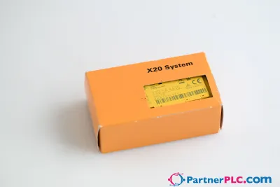
 UsadoB&R 5C5001.01 IPC 5000 5D5500.06 Used
 UsadoB&R 5PC720.1505-K07 - 5P62:0A-03 Used